Device with microbubble-induced superhydrophobic surfaces for drag reduction and biofouling prevention and device for biofouling prevention

a microbubble and superhydrophobic technology, which is applied in the direction of special-purpose vessels, vessel construction, transportation and packaging, etc., can solve the problems of not providing the drag reduction effect, the microbubbles cannot cover most of the hull surface, and the drag reduction effect of the microbubble drag reduction device is less than 2% on the actual ship

Inactive Publication Date: 2012-10-04
WU KEE RONG +4
View PDF2 Cites 18 Cited by
  • Summary
  • Abstract
  • Description
  • Claims
  • Application Information

AI Technical Summary

Benefits of technology

[0028]FIG. 5 shows slip effect between the seawater and the hull surface below the sea surface, wherein the arrows indicate the velocity gradient of the seawater relative to the hull.
[0029]FIG. 6 sh...

Problems solved by technology

Thus, how to reduce the frictional resistance RF so as to reduce the energy consumption for moving a ship has been an important issue in fluid dynamic research of ships.
However, the drag reducing effect of the microbubble drag reduction devices on an actual ship is less than 2%.
1. The diameters of the bubbles generated by the porous plates are so large that the bubbles overlap and become larger due to buoyant effect. The larger bubbles could adhere to the hull surface and increase the resistance to the hull. On the other hand, the larger bubbles could escape and, thus, could not remain in the effective boundary layer. As a result, the larger bubbles move to the water surface and, thus, fail to provide the drag reducing effect.
2. The area of the hull surface of the actual ship covered by the porous plates is too small (see FIG. 2A), such that the microbubbles could not cover most of the hull surface below the water surface.
3. When the amount of air supplied to the porous plates is increased, the microbubbles are apt to overflow out of the boundary layer under the action of vertical velocity that is created while injecting the microbubbles into the flow field around the hull, leading to adverse affect to the drag reducing efficiency.
However, two side boards D of the bottom plate B intended for restraining the microbubbles and preventing overflow of the microbubbles cause low utility ratio of the microbubbles.
In addition to the low drag reducing efficiency, the conventional microbubble drag reduction device incurs many structural safety problems including the risks of sealing of the hull, corrosion of the hull, and biofouling of marine organisms.
Further, the bubbles injected into the seawater reduce the propelling efficiency of the vanes of the propeller by about 3% and cause surface cavitation corrosion of the vanes.
However, the amount of air generated is too small, and the energy conversion ratio of the energy saved in reducing drag to the inputted electricity is small.
On the other hand, some marine organisms love to adhere to the hull surface that is continually submerged below the water surface, increasing the roughness of the hu...

Method used


Image

  • Device with microbubble-induced superhydrophobic surfaces for drag reduction and biofouling prevention and device for biofouling prevention
  • Device with microbubble-induced superhydrophobic surfaces for drag reduction and biofouling prevention and device for biofouling prevention
  • Device with microbubble-induced superhydrophobic surfaces for drag reduction and biofouling prevention and device for biofouling prevention

Examples


Embodiment Construction

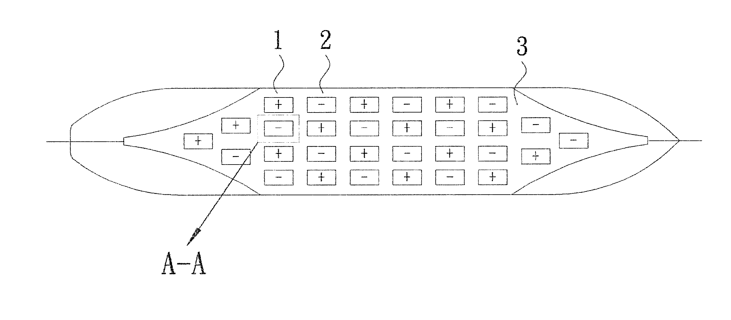
[0037]With reference to FIGS. 3A, 3B, 4A, 4B, 5, and 6, a device with microbubble-induced superhydrophobic surfaces for drag reduction and biofouling prevention includes a plurality of anodic microporous plates 1 and a plurality of cathodic microporous plates 2 mounted to a hull surface of a ship. In this embodiment, the anodic microporous plates 1 and the cathodic microporous plates 2 are mounted to a bottom plate 3 of the hull. Each of the anodic microporous plates 1 and the cathodic microporous plates 2 includes a surface having a plurality of micropores 4. The structure of each cathodic microporous plate 2 is identical to that of each anodic microporous plate 1, which is shown in FIG. 6. The device with microbubble-induced superhydrophobic surfaces for drag reduction and biofouling prevention further includes a direct current (DC) power supply 5. The DC power supply 5 includes a positive pole electrically connected to each anodic microporous plate 1 and a negative pole electrica...


PUM


Abstract

A device with microbubble-induced superhydrophobic surfaces for drag reduction and biofouling prevention includes an anodic microporous plate, a cathodic microporous plate, and a DC power supply. The anodic microporous plate and the cathodic microporous plate are mounted to a hull surface of a ship. The DC power supply includes a positive pole electrically connected to the anodic microporous plate and a negative pole electrically connected to the cathodic microporous plate. Seawater is electrolyzed to generate hydrogen microbubbles adjacent to a surface of the cathodic microporous plate and to generate oxygen microbubbles adjacent to a surface of the anodic microporous plate, forming superhydrophobic surfaces on the surfaces of the anodic microporous plate and the cathodic microporous plate. Electric current flows through the anodic microporous plate and the cathodic microporous plate to prevent biofouling.

Description

BACKGROUND OF THE INVENTION[0001]The invention relates to a device with microbubble-induced superhydrophobic surfaces for drag reduction and biofouling prevention and a device for biofouling prevention.[0002]Overcoming resistances is the basic requirement for ships. FIGS. 1A and 113 show a ship moving at a speed V. The resistances to the ship include about 85%-95% of frictional resistance RF and wave making resistance RW, about 3%-5% of vortex flow loss RE, and 2% (for a low-speed ship) to 10% (for a high-speed ship) of air resistance RA. The affect of the frictional resistance RF to a low-speed ship (about 15 nautical miles per hour) is significant and may be up to 90%.[0003]Thus, how to reduce the frictional resistance RF so as to reduce the energy consumption for moving a ship has been an important issue in fluid dynamic research of ships. Many methods for reducing the frictional resistance RF, such as surface structure with riblets for biomimetic drag reduction, artificial micro...

Claims


Application Information

Patent Timeline
IPC IPC(8): B63B1/38
CPCB63B1/38Y02T70/122B63B59/04Y02T70/10
Inventor WU, KEE-RONGSHYU, YU-TSUENHUNG, CHUNG-HSUANGSUN, JUI-CHINGWU, JIING-KATE
Owner WU KEE RONG
Why Eureka
Try Eureka