Organic electroluminescence device

Active Publication Date: 2012-10-04
IDEMITSU KOSAN CO LTD
View PDF4 Cites 128 Cited by
  • Summary
  • Abstract
  • Description
  • Claims
  • Application Information

AI Technical Summary

Benefits of technology

[0021]An organic EL device of the invention efficiently emits light even in a practically high c

Problems solved by technology

However, as compared with phosphorescent emission, the fluorescent emission is still problematic on improving efficiency.
Accordingly, it is considered that many practical problems in using

Method used


Image

  • Organic electroluminescence device
  • Organic electroluminescence device
  • Organic electroluminescence device

Examples


synthesis example 1

Synthesis of GH-4

[0184]Under an argon gas atmosphere, an intermediate A (4.4 g, 21 mmol) synthesized according to the method described in JP-A-2010-180204, an intermediate B (4.7 g, 10 mmol) synthesized according to the method described in International Publication No. WO03 / 080760, tris(dibenzylidene acetone)dipalladium (0.37 g, 0.4 mmol), tri-t-butylphosphonium tetrafluoroborate (0.46 g, 1.6 mmol), t-butoxysodium (2.7 g, 28 mmol) and anhydrous toluene (100 ml) were sequentially added and refluxed for eight hours.

[0185]After the reaction solution was cooled down to the room temperature, an organic layer was separated and an organic solvent was distilled away under reduced pressure. The obtained residue was refined by silica-gel column chromatography, so that a target compound GH-4 (3.6 g, a yield of 50%) was obtained.

[0186]FD-MS analysis consequently showed that m / e was equal- to 722 while a calculated molecular weight was 722.

[0187]A synthesis scheme of the target compound GH-4 is ...

synthesis example 2

Synthesis of BH-1

[0188]

[0189]Under a nitrogen gas atmosphere, to a flask, 3,6-dibromocarbazole (5 g, 15.4 mmol), phenylboronic acid (4.1 g, 33.9 mmol), tetrakis(triphenylphosphine)palladium (0.7 g, 0.6 mmol), toluene (45 ml) and 2M sodium carbonate (45 ml) were mixed in sequence, and were stirred for eight hours at 80 degrees C. An organic phase was separated and then concentrated under reduced pressure by an evaporator. The obtained residue thereof was refined by silica-gel column chromatography, so that 3,6-diphenylcarbazole (3.6 g, a yield of 74%) was obtained.

[0190]Under an argon gas atmosphere, 2,6-dichloropyrazine (0.6 g, 3.9 mmol), 3,6-dibromocarbazole (2.6 g, 8 mmol), tris(dibenzylideneacetone)dipalladium (0.07 g, 0.08 mmol), tri-t-butylphosphonium tetrafluoroborate (0.09 g, 0.3 mmol), sodium t-butoxide (0.5 g, 5.5 mmol), and anhydrous toluene (20 ml) were mixed in sequence, and heated to reflux for 8 hours.

[0191]After the reaction solution was cooled down to the room temper...

example 1

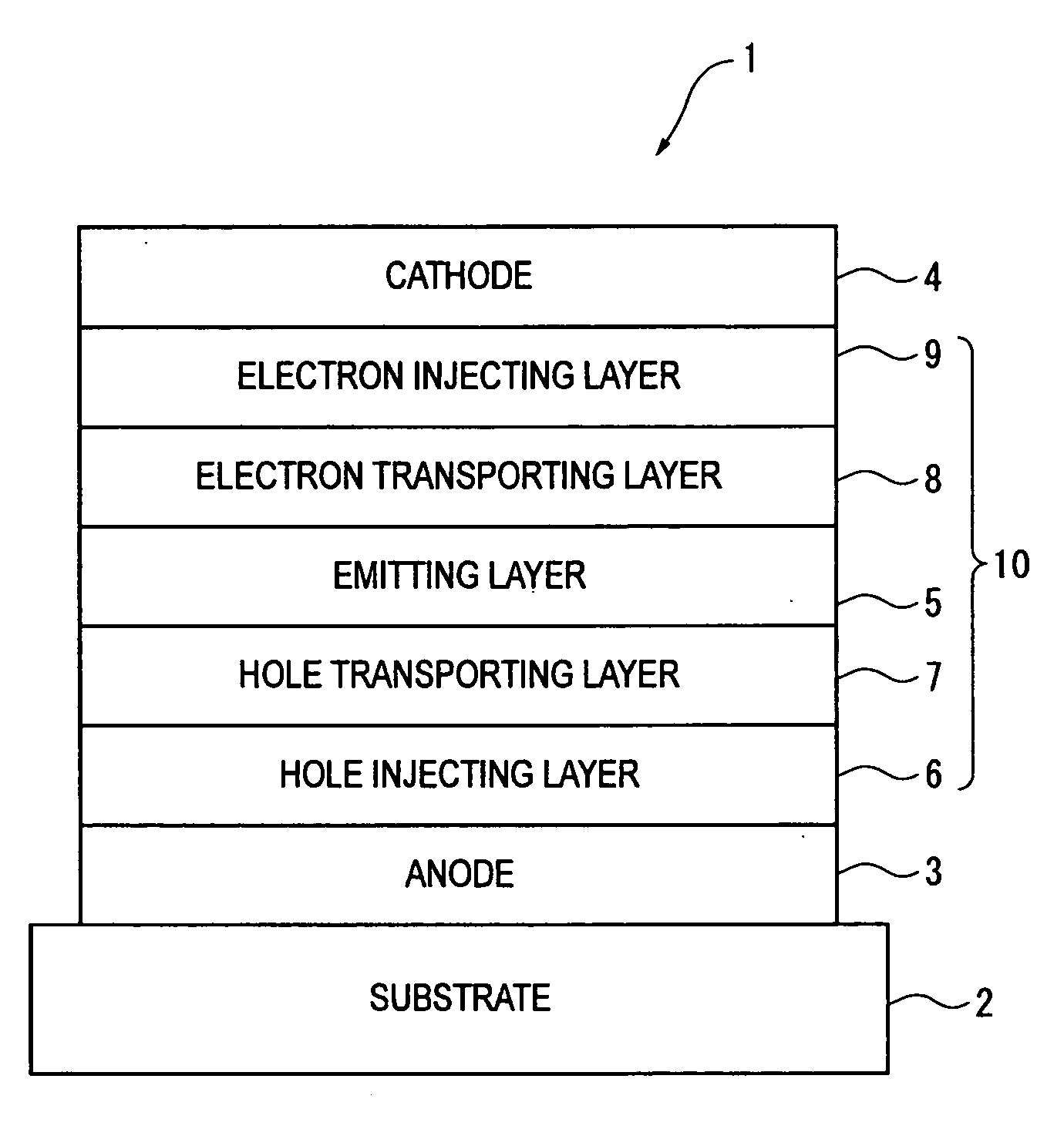
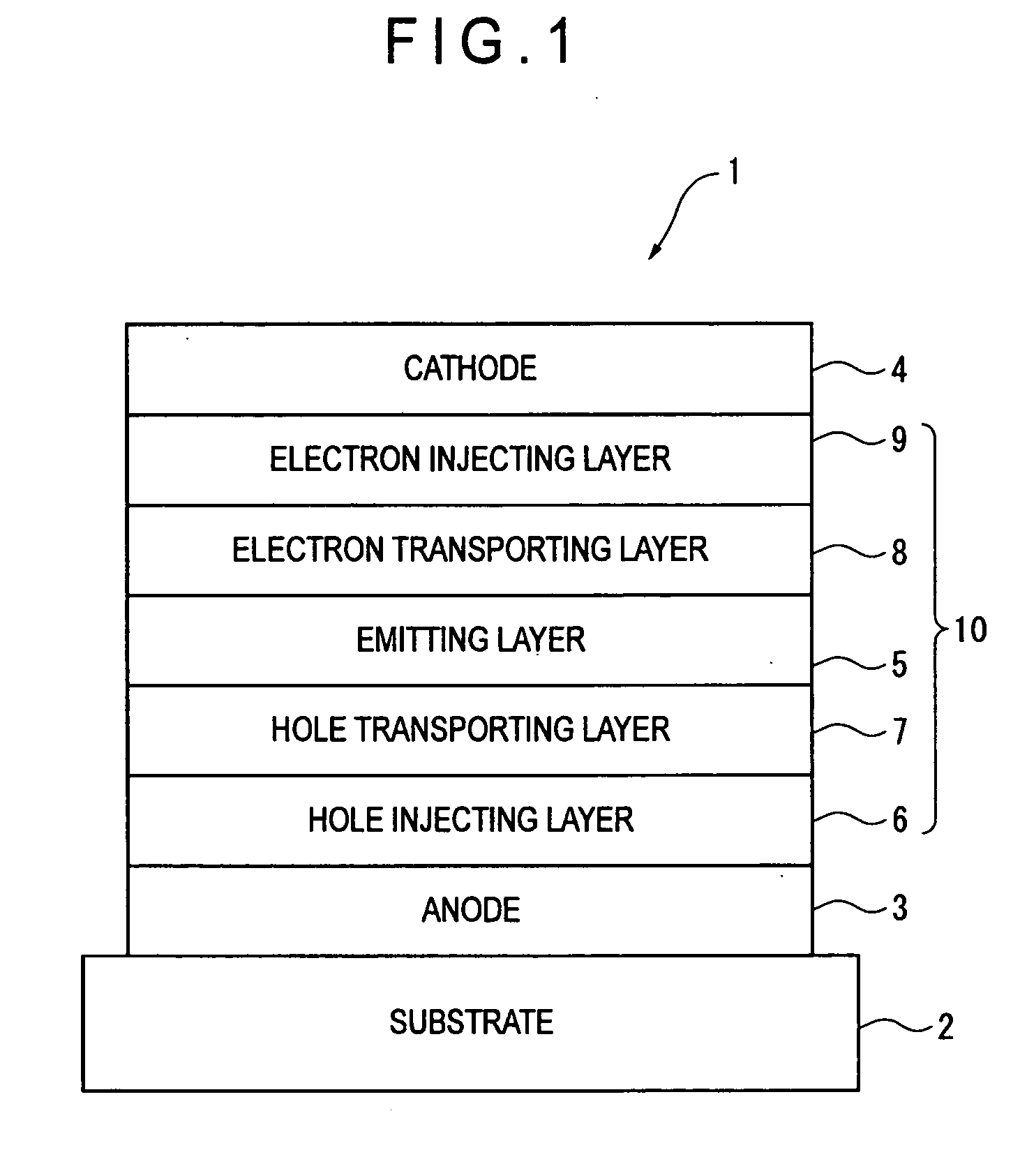
[0218]A glass substrate (size: 25 mm×75 mm×1.1 mm thick, manufactured by Geomatec Co., Ltd.) having an ITO transparent electrode (anode) was ultrasonic-cleaned in isopropyl alcohol for five minutes, and then UV / ozone-cleaned for 30 minutes. A film of ITO was 130 nm thick.

[0219]After the glass substrate having the transparent electrode line was cleaned, the glass substrate was mounted on a substrate holder of a vacuum evaporation apparatus. Initially, the compound HI-1 was evaporated on a surface of the glass substrate where the transparent electrode line was provided in a manner to cover the transparent electrode, thereby forming a 50-nm thick film of the compound HI-1. The HI-1 film serves as a hole injecting layer.

[0220]After the film formation of the HI-1 film, a compound HT-1 was evaporated on the HI-1 film to form a 60-nm thick HT-1 film. The HT-1 film serves as a hole transporting layer.

[0221]The compound GH-4 (the host material) and the compound GD-1 (the fluorescent dopant m...


PUM


Abstract

An organic EL device includes a pair of electrodes and an organic compound layer between pair of electrodes. The organic compound layer includes an emitting layer including a first material and a second material. The second material is a fluorescent material. Singlet energy EgS(H) of the first material and singlet energy EgS(D) of the second material satisfy a relationship of the following formula (1). The first material satisfies a relationship of the following formula (2) in terms of a difference ΔST(H) between the singlet energy EgS(H) and an energy gap Eg77K(H) at 77K.
EgS(H)>EgS(D)  (1)
ΔST(H)=EgS(H)−Eg77K(H)<0.3 (eV)  (2)

Description

[0001]The entire disclosure of Japanese Patent Application No. 2011-068758, filed Mar. 25, 2011, and U.S. Provisional Application No. 61 / 467,703, filed Mar. 25, 2011, is expressly incorporated by reference herein.BACKGROUND OF THE INVENTION[0002]1. Field of the Invention[0003]The present invention relates to an organic electroluminescence device.[0004]2. Description of Related Art[0005]When voltage is applied on an organic electroluminescence device (hereinafter, referred to as an organic EL device), holes and electrons are respectively injected into an emitting layer from an anode and a cathode. The injected electrons and holes are recombined in an emitting layer to form excitons. Here, according to the electron spin statistics theory, singlet excitons and triplet excitons are generated at a ratio of 25%:75%. In the classification according to the emission principle, in a fluorescent EL device which uses emission caused by singlet excitons, the limited value of an internal quantum ...

Claims


Application Information

Patent Timeline
IPC IPC(8): H05B33/14
CPCH01L51/5012H01L2251/552H01L51/0059H01L51/0067H01L51/0072H01L51/5004H01L51/006H10K85/631H10K85/654H10K85/633H10K85/6572H10K50/11H10K2101/40H10K2101/30C07D401/14C07D403/14C09K11/025C09K11/06H10K2101/20H10K2101/27H10K85/615C09K2211/1007C09K2211/1011C09K2211/1014
Inventor OGIWARA, TOSHINARIHOSOKAWA, CHISHIO
Owner IDEMITSU KOSAN CO LTD
Why Eureka
Try Eureka