Two-stage single phase bi-directional pwm power converter with DC link capacitor reduction

a power converter and dc link technology, applied in the direction of dc-ac conversion without reversal, dc source parallel operation, ac network load balancing, etc., can solve the problems of reducing the potential reducing the power density of the converter, and substantial voltage ripple voltage on the dc side of the converter, so as to reduce the dc link capacitance and improve the power density. , the effect of low d

a power converter and dc link technology, applied in the direction of dc-ac conversion without reversal, dc source parallel operation, ac network load balancing, etc., can solve the problems of reducing the potential reducing the power density of the converter, and substantial voltage ripple voltage on the dc side of the converter, so as to reduce the dc link capacitance and improve the power density. , the effect of low d

US20120257429A1Active Publication Date: 2012-10-11VIRGINIA TECH INTPROP INC

Image

  • Two-stage single phase bi-directional pwm power converter with DC link capacitor reduction
  • Two-stage single phase bi-directional pwm power converter with DC link capacitor reduction
  • Two-stage single phase bi-directional pwm power converter with DC link capacitor reduction

Examples


Embodiment Construction

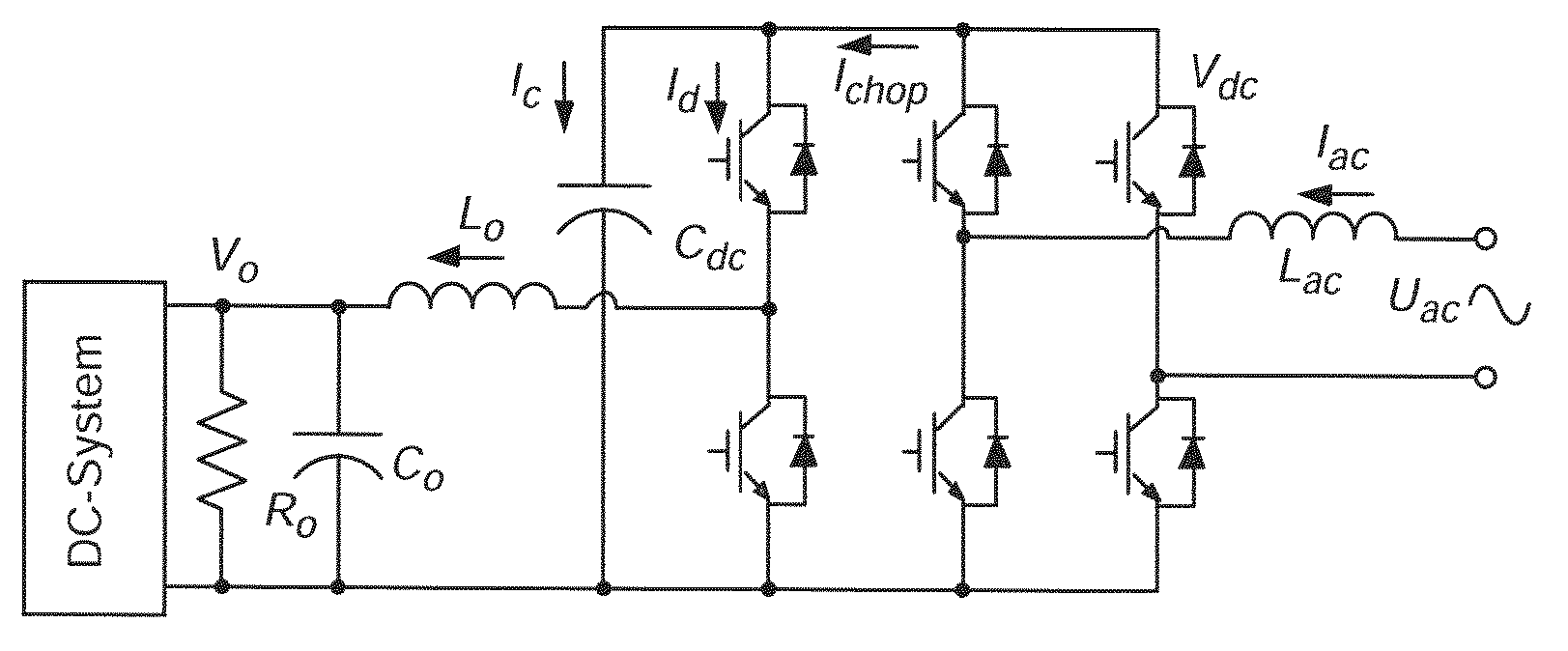
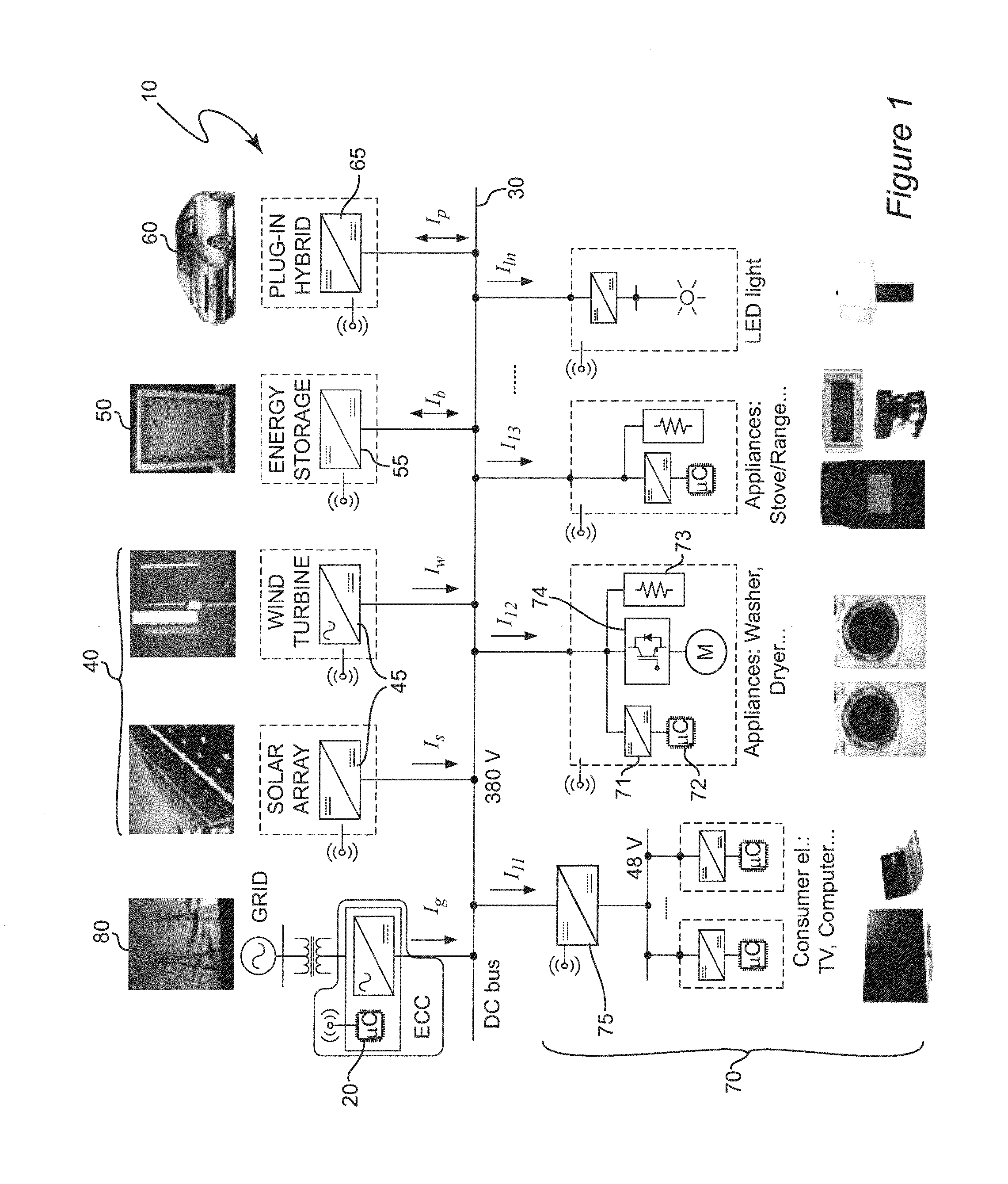
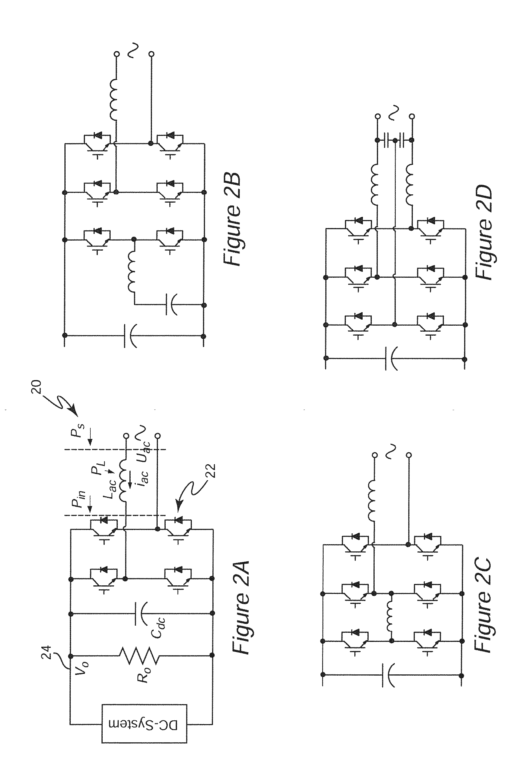
[0036]Referring now to the drawings, and more particularly to FIG. 1, there is shown, in highly schematic form, a generalized depiction of a DC nanogrid 10 which is an exemplary environment for application of the invention, generally depicted at 20. It should be understood that FIG. 1 is arranged to facilitate an understanding of the application of the invention and no portion of FIG. 1 is admitted to be prior art in regard to the present invention.

[0037]Essentially, a DC nanogrid is a power distribution grid which is generally very limited in geographic extent (e.g. limited to a building or one or a limited number of residences or a vehicle such as a ship or aircraft) in which power is distributed over DC bus 30 at a nominal DC voltage of 380 volts although other nominal voltages can be employed and, in any case, the nominal design voltage is unimportant to the successful practice of the invention. It should be understood that DC bus 30 can also be embodied as a plurality of DC bus...


PUM


Abstract

DC link capacitance in a bi-directional AC / DC power converter using a full-bridge or H-bridge switching circuit can be greatly reduced and the power density of the power converter correspondingly increased by inclusion of a bi-directional synchronous rectifier (SR) DC / DC converter as a second stage of the power converter and controlling the second stage with a control loop having a transfer function common to both buck and boost modes of operation of the bi-directional SR DC / DC converter and a resonant transfer function to increase gain at the ripple voltage frequency (twice the AC line frequency) to control the duty cycle of the switches of the bi-directional SR DC / DC stage and controlling the duty cycle of the switches of the full-bridge or H-bridge switching circuit using a control loop including a notch filter at the ripple voltage frequency.

Description

CROSS-REFERENCE TO RELATED APPLICATIONS[0001]This application claims benefit of priority of U.S. Provisional Application 61 / 473,399, filed Apr. 8, 2011, which is hereby incorporated by reference in its entirety.FIELD OF THE INVENTION[0002]The present invention generally relates to Power supplies and power converters and, more particularly, to bi-directional AC / DC power converters which are particularly useful for interfacing a DC based distribution system and / or renewable energy sources to an AC power distribution grid.BACKGROUND OF THE INVENTION[0003]At the present time, most electrical power is generated by relatively large power plants operating on fossil or nuclear fuels or hydroelectric power plants for which relatively few suitable locations exist naturally or can be developed. The distribution of such facilities and the variations in demand for power in different geographic regions requires distribution of generated alternating current (AC) power over a network of power trans...

Claims


Application Information

Patent Timeline
11 Oct 2012
Publication
US20120257429A1
IPC
H02M7/217; H02M7/5387
CPC
H02J1/10; H02J3/32; H02M3/1582; H02M7/48; H02M2001/007; H02M7/797; H02J3/383; H02J3/386
Inventors
DONG, DONG; BOROYEVICH, DUSHAN