Metal microparticle dispersion, process for production of electrically conductive substrate, and electrically conductive substrate

a technology of metal microparticles and substrates, which is applied in the direction of non-conductive materials with dispersed conductive materials, resistive material coatings, plasma techniques, etc., can solve the problems of large number of steps, high cost, and high cost, and achieves high dispersion, easy removal, and stable maintenance

Active Publication Date: 2012-10-25
DAI NIPPON PRINTING CO LTD
View PDF11 Cites 12 Cited by
  • Summary
  • Abstract
  • Description
  • Claims
  • Application Information

AI Technical Summary

Benefits of technology

[0024]In the metal microparticle dispersion of the present invention, the metal microparticles have a high dispersibility, and the above dispersibility is stably maintained. Further, since when preparing the electrically conductive substrate, the organic matters can readily be removed by burning at low temperature, sintering is liable to go on, and the electrically conductive substrate which is excellent in an electrical conductivity can be obtained. Also, since when producing the electrically conductive substrate by a microwave surface wave plasma, the organic matters originating in the dispersion medium can be removed by the above microwave surface wave plasma treatment, and a burning step for removing the organic matters does not have to be provided separately, so that the production process can be simplified. Thus, according to the production process for an electrically conductive substrate by using the metal microparticle dispersion of the present invention, the electrically conductive substrate which is excellent in an electrical conductivity can efficiently be produced.

Problems solved by technology

However, the above method has the defects that it has a large number of steps and is complicated and that a photoresist material is needed.
However, if the burning temperature is 200° C. or higher, the above method can not be used when a low heat resistant base material such as a polyester resin and the like is used since deformation, decoloration and the like are brought about on the base material.
That is, if primary particles of the copper microparticles stay in a state in which they are notably aggregated or a size and a form of secondary particles thereof are uneven, defects are liable to be brought about when forming circuits and the like.

Method used


Image

  • Metal microparticle dispersion, process for production of electrically conductive substrate, and electrically conductive substrate
  • Metal microparticle dispersion, process for production of electrically conductive substrate, and electrically conductive substrate
  • Metal microparticle dispersion, process for production of electrically conductive substrate, and electrically conductive substrate

Examples


production example 1a

Metal Microparticle Dispersion

[0146]A Lion diffusion pump oil A (manufactured by Lion Corporation) 360 g which was a low vapor pressure liquid was used as a dispersant, and Solsperse 39000 (principal chain: polyethyleneimine skeleton, side chain: having 6 valerolactone units on an average and 6 caprolactone units on an average in three side chains, manufactured by Lubrizol Corporation) 40 g which was a polymeric dispersant was added thereto and stirred to obtain a polymeric dispersant-containing dispersion medium.

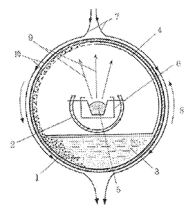
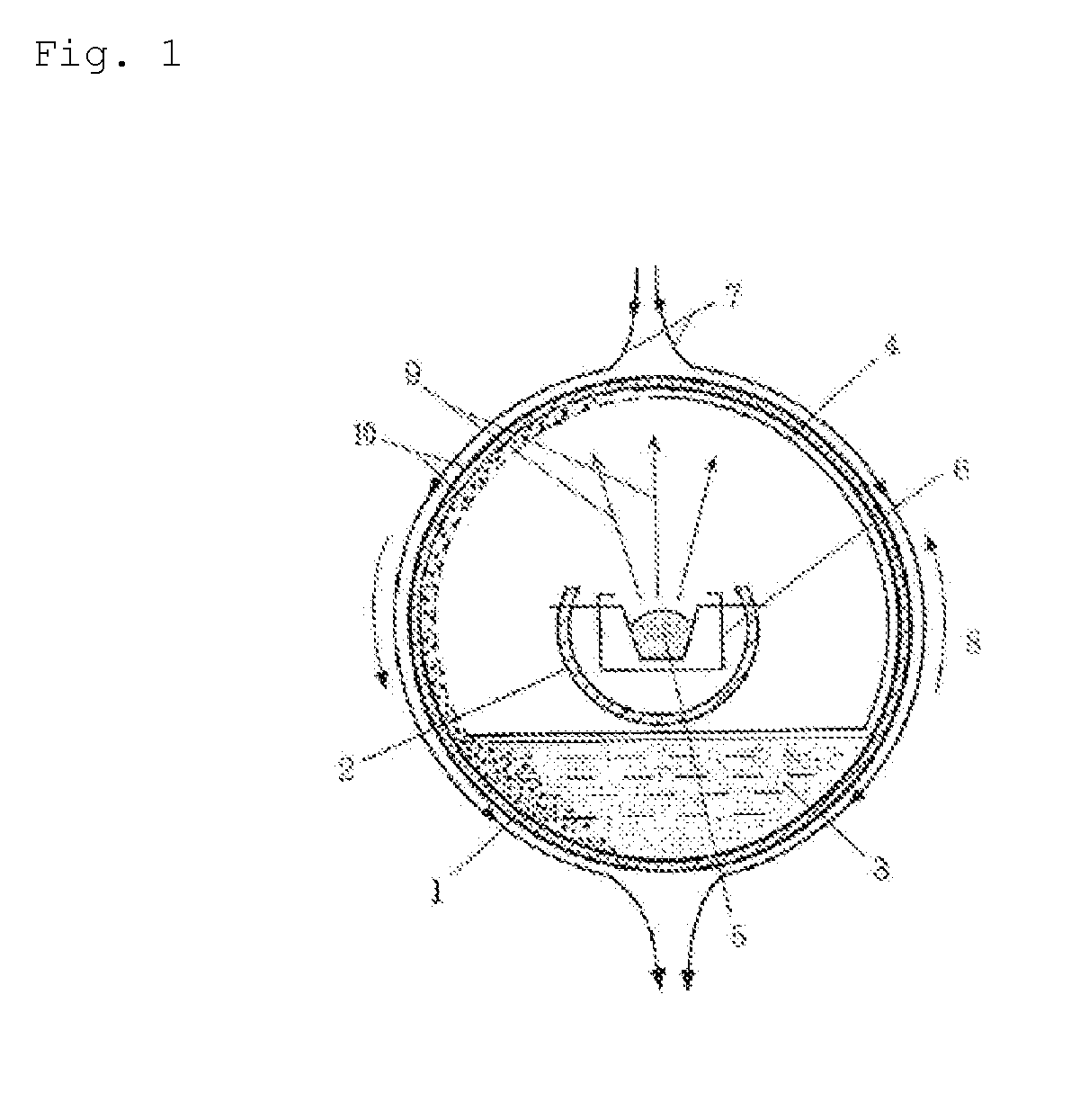
[0147]Metal copper was used to produce a metal microparticle dispersion by means of an equipment shown in FIG. 1. That is, 5 g of a granulated copper lump (manufactured by Fruuchi Chemical Corporation) was put in a vessel 6, and the dispersion medium described above was put in a rotary drum type chamber 1. A pressure in an inside of the chamber was reduced to 10−3 Pa by vacuuming by means of a vacuum pump. Then, the chamber was rotated while cooling by flowing water, and an...

production example 2a

Metal Microparticle Dispersion

[0151]A silver microparticle dispersion was prepared in the same manner as in Production Example 1A, except that 5 g of silver (manufactured by Ishifuku Metal Industry Co., Ltd.) was used in place of copper used in Production Example 1A. The above dispersion was filtrated through a filter of 0.2 μm and observed by means of STEM in the same manner as in Production Example 1A, and as a result thereof, silver microparticles having an average primary particle diameter of 10 nm could be confirmed.

production example 3a

Metal Microparticle Dispersion

[0152]A copper microparticle dispersion was prepared in the same manner as in Production Example 1A, except that in Production Example 1A, Solsperse 71000 (principal chain: polyethyleneimine skeleton, side chain: having 15 polypropylene glycol units on an average and 2 ethylene glycol units on an average in four side chains, manufactured by Lubrizol Corporation) was used as the polymeric dispersant in place of Solsperse 39000. The above dispersion was filtrated through a filter of 0.2 μm and observed by means of STEM in the same manner as in Production Example 1A, and as a result thereof, copper microparticles having an average primary particle diameter of 8 nm could be confirmed.


PUM

PropertyMeasurementUnit
average primary particle diameteraaaaaaaaaa
particle diameteraaaaaaaaaa
temperatureaaaaaaaaaa

Abstract

Provided are a metal microparticle dispersion which is excellent in a dispersibility, an electrically conductive substrate which is obtained by using the above metal microparticle dispersion and which is excellent in an electrical conductivity and a production process for the same.
Provided is a metal microparticle dispersion comprising metal microparticles, a polymeric dispersant and a dispersion medium, wherein an average primary particle diameter of the metal microparticles is 0.001 to 0.5 μm; the polymeric dispersant has a polyester skeleton in at least one of a principal chain and a side chain thereof; the above polyester skeleton has at least one of a constitutional unit derived from valerolactone and a constitutional unit derived from caprolactone, and a sum of the numbers of the above constitutional units is 10 or more in terms of an average value, or the polymeric dispersant has a polyether skeleton in at least one of a principal chain and a side chain thereof; and a content of the above polymeric dispersant is 0.1 to 100 parts by mass based on a content of 100 parts by mass of the metal microparticles. Further, provided is a production process for an electrically conductive substrate, comprising printing a coating solution containing the above metal microparticle dispersion in a pattern-like form to form a printed layer and subjecting the above printed layer to burning treatment to form a pattern-like metal microparticle sintered film, and an electrically conductive substrate produced by the above production process is provided as well.

Description

BACKGROUND OF THE INVENTION[0001]The present invention relates to a metal microparticle dispersion having a high dispersibility, a production process for an electrically conductive substrate carried out by using the above metal microparticle dispersion and an electrically conductive substrate obtained by the above production process.RELATED ART[0002]A method in which a photoresist and the like are coated on a base material having a metal foil stuck thereon and in which the photoresist is exposed through a desired circuit pattern to form the pattern by chemical etching has so far been used in order to produce a circuit board in which electrically conductive wirings are provided on a base material. In the above method, a metal foil can be used as an electrically conductive wiring, and therefore an electrically conductive substrate having a small volume resistivity and a high performance can be produced. However, the above method has the defects that it has a large number of steps and ...

Claims


Application Information

Patent Timeline
Patent Type & Authority Applications(United States)
IPC IPC(8): H01B1/02H05K3/12H01B1/04H05K1/09B22F1/0545B22F1/107
CPCH05K1/097B22F1/0022B82Y30/00B22F3/1055B22F2003/1054B22F1/0074Y02P10/25B22F1/0545B22F1/107B22F12/30B22F10/28B22F10/32C23C16/455H05K3/125
Inventor HOJO, MIKIKOYONEDA, SHINYAYOSHI, NAONOBUSATO, TAKESHIMATSUMOTO, KISEI
Owner DAI NIPPON PRINTING CO LTD
Why Eureka
Try Eureka