
Atomic Layer Deposition Apparatus and Process

Active Publication Date: 2012-10-25
KURT J LESKER
View PDF48 Cites 164 Cited by
  • Summary
  • Abstract
  • Description
  • Claims
  • Application Information

AI Technical Summary

Benefits of technology

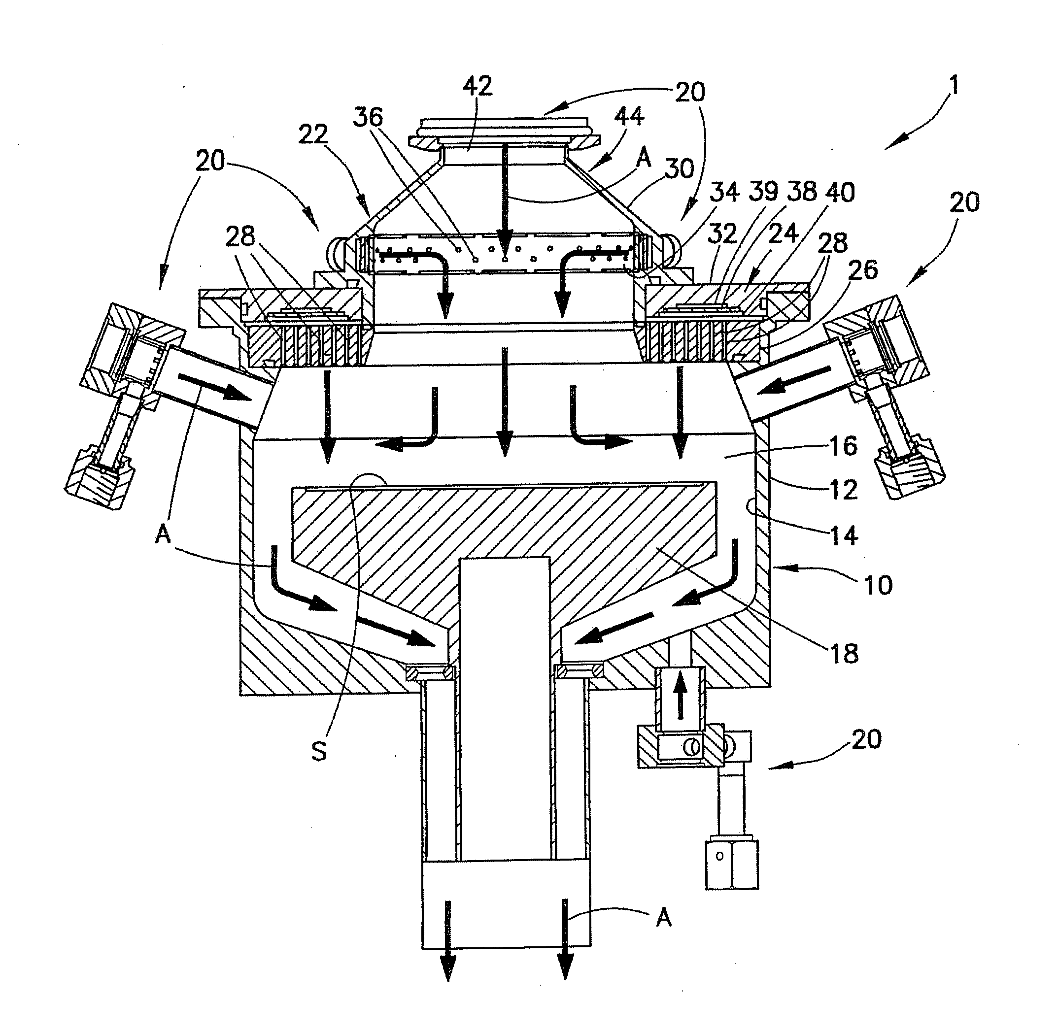
[0025]Generally, provided is an atomic layer deposition apparatus and process that overcomes or addresses some or all of the above-discussed deficiencies and drawbacks associated with existing atomic layer deposition systems. Preferably, provided is an atomic layer deposition apparatus and process that provides improved deposition characteristics for the fabrication of wafers in both research and development and production applications. Preferably, provided is an atomic layer deposition apparatus and process that facilitates the effective growth of a thin film onto a substrate. Preferably, provided is an atomic layer deposition apparatus and method that provides plasma-enhanced atomic layer deposition. Preferably, provided is an atomic layer deposition apparatus and process that leads to beneficial focusing of precursor gases towards a substrate. Preferably, provided is an atomic layer deposition apparatus and process that creates a curtain gas area that prevents or minimizes contact between injected gas and an inner surface of a wall or port of a chamber.
[0028]In a further preferred and non-limiting embodiment, provided is an atomic layer deposition process, including: removably positioning a substrate within an internal volume of a chamber; introducing precursor gas into the internal volume of the chamber through at least one gas injection port; and introducing inactive gas into the internal volume of the chamber through at least one inactive gas dispersion arrangement comprising a primary dispersion member having a thickness and a plurality of holes extending therethrough, such that at least a portion of the inactive gas introduced to the internal volume of the chamber through the plurality of holes substantially concentrically focuses the precursor gas towards a surface of the substrate.

Problems solved by technology

Once the surface becomes fully passivated, reactions are complete and result in the formation of a limited number of new surface species.
Outside of this temperature window, growth becomes non-ideal.
At temperatures below the ALD window, thermal energy at the substrate surface becomes insufficient for surface reactions and / or to prevent physical adsorption (or condensation) of precursor molecules.
Thermal self-decomposition of precursor molecules and / or desorption of chemically-adsorbed surface species result in non-ideal growth at higher substrate temperatures.
One known limitation of existing ALD processing is the relatively low throughput due to long process times when compared to PVD and conventional CVD methods.
Another disadvantage is the limited number of precursors presently available and, therefore, materials deposited by ALD methods.
These sources of non-uniformity include overlapping of precursor pulses, non-uniform precursor delivery, and precursor thermal self-decomposition.
In addition, reaction byproducts have been shown to contribute to film non-uniformity.
Adequate purging between precursor pulse steps is critical, since overlapping of pulses results in parasitic CVD surface reactions that decrease film uniformity and increase the potential for gas phase reactions and associated film defects.
Furthermore, ALD surface chemistry is not always ideal, such that film uniformity depends on distribution of precursor across the substrate surface during pulse steps.
Plasma source integration, in general, increases process chamber design complexity and volume.
It is also very important to prevent deposition of absorbing layers on this surface, since this will result in attenuation of the RF signal and subsequent plasma source failure.
Isolation of the plasma generation region from precursors (other than plasma process gases) may be achieved by incorporating an isolation valve; however, the cycling of an isolation valve during ALD can produce particles resulting in unwanted film defects.
Like plasma, the integration of these features increases chamber design complexity and volume.
Problems associated with the integration of chamber ports necessary for SE include coating of the transparent windows resulting in attenuation of transmitted light, as well as more complex chamber geometry and additional volume that increases required purge times.
Similar to ports for SE integration, this additional port for substrate transfer increases chamber design complexity and volume and, therefore, required purge times.
In some cases, these relatively simple systems enable thermal processes only and have no diagnostic or vacuum transfer capability.
First, for plasma to be “remote” there must necessarily be sufficient spatial separation between the plasma generation region and substrate surface.
In addition, spatial confinement of the plasma results in quenching of active species necessary for ALD surface reactions.
These enhanced system features, however, significantly increase process chamber design complexity to maintain ALD process performance.
If these gate valves are not closed during precursor pulse steps, then the transparent windows for SE light transmission can become coated, resulting in limited ability to monitor process due to signal attenuation.
Similar signal attenuation issues can occur when the remote plasma source is not properly protected during precursor pulse steps.
This is due to deposition of absorbing materials on the transparent dielectric window resulting in plasma source failure.
According to certain existing systems, the cycling of mechanical valves during processing can generate particles that result in unwanted film defects.
In particular, remote plasma source isolation can be most problematic since a gate valve is typically positioned directly above the substrate surface where particles tend to rain down onto the surface when the valve is cycled.
In cases where an inactive gas barrier is used to prevent film deposition inside the plasma source (without the use of a mechanical gate valve), it is still difficult to prevent diffusion of certain precursors into the plasma port during precursor pulse steps.
During precursor pulse steps, water diffusion and subsequent condensation inside the remote plasma port can become a source of parasitic CVD that severely limits thermal ALD process performance.
In summary, there are many challenges associated with the integration of various ALD apparatus design features.
Due to more complex process chamber geometry, as well as additional volume requirements, these enhanced system features significantly increase apparatus design complexity to maintain ALD process performance (e.g., uniformity and cycle times).
Additional challenges associated with remote plasma integration include plasma performance issues associated with exposure of internal plasma source components to ALD precursors (other than plasma process gases).
Similar challenges are associated with the integration of analytical ports necessary for SE, where exposure of internal components to ALD precursors can result in issues with feature performance.

Method used


Image

  • Atomic Layer Deposition Apparatus and Process
  • Atomic Layer Deposition Apparatus and Process
  • Atomic Layer Deposition Apparatus and Process

Examples


Embodiment Construction

[0050]For purposes of the description hereinafter, the terms “end”, “upper”, “lower”, “right”, “left”, “vertical”, “horizontal”, “top”, “bottom”, “lateral”, “longitudinal” and derivatives thereof shall relate to the invention as it is oriented in the drawing figures. However, it is to be understood that the invention may assume various alternative variations and step sequences, except where expressly specified to the contrary. It is also to be understood that the specific devices and processes illustrated in the attached drawings, and described in the following specification, are simply exemplary embodiments of the invention. Hence, specific dimensions and other physical characteristics related to the embodiments disclosed herein are not to be considered as limiting.

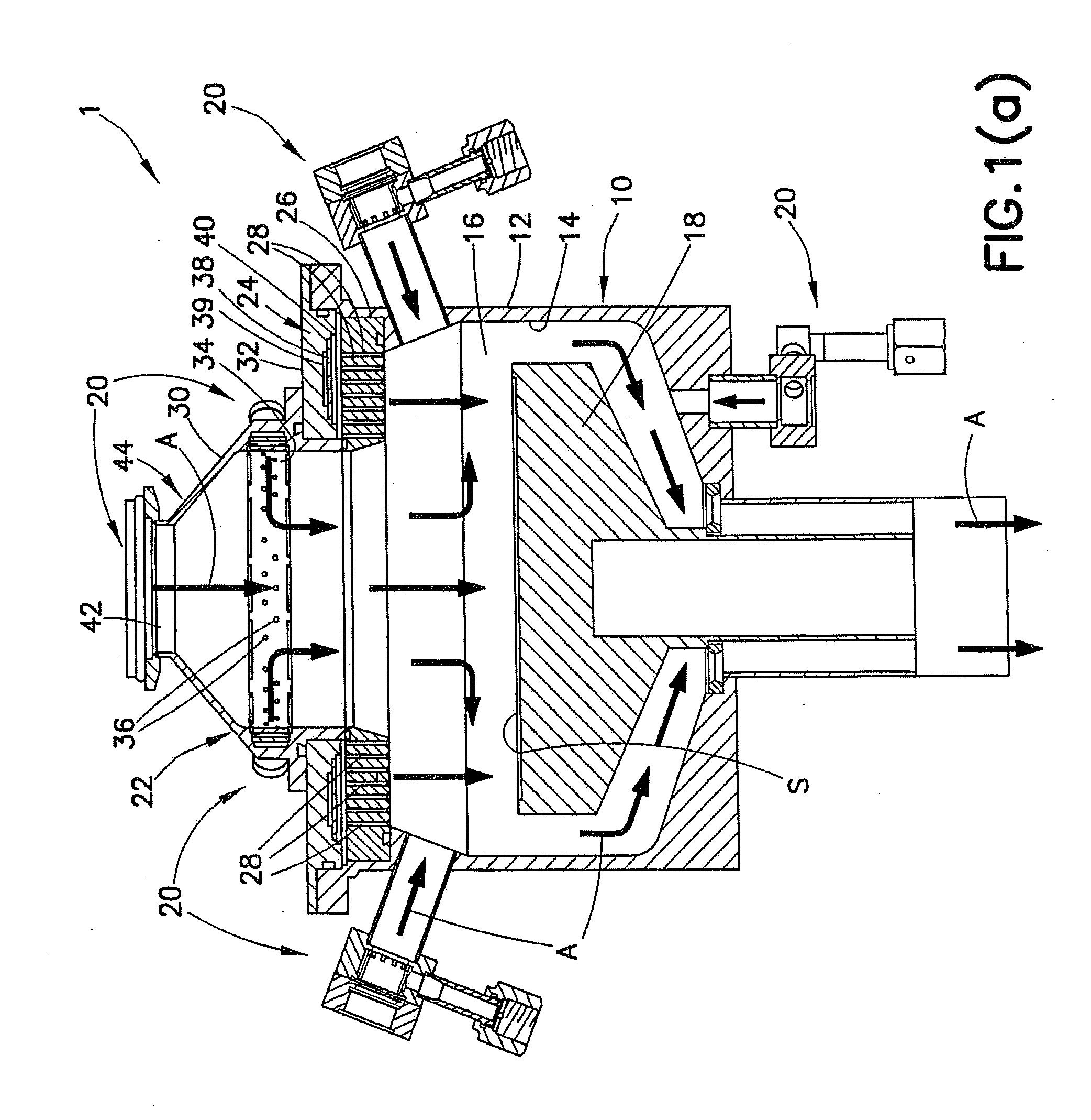
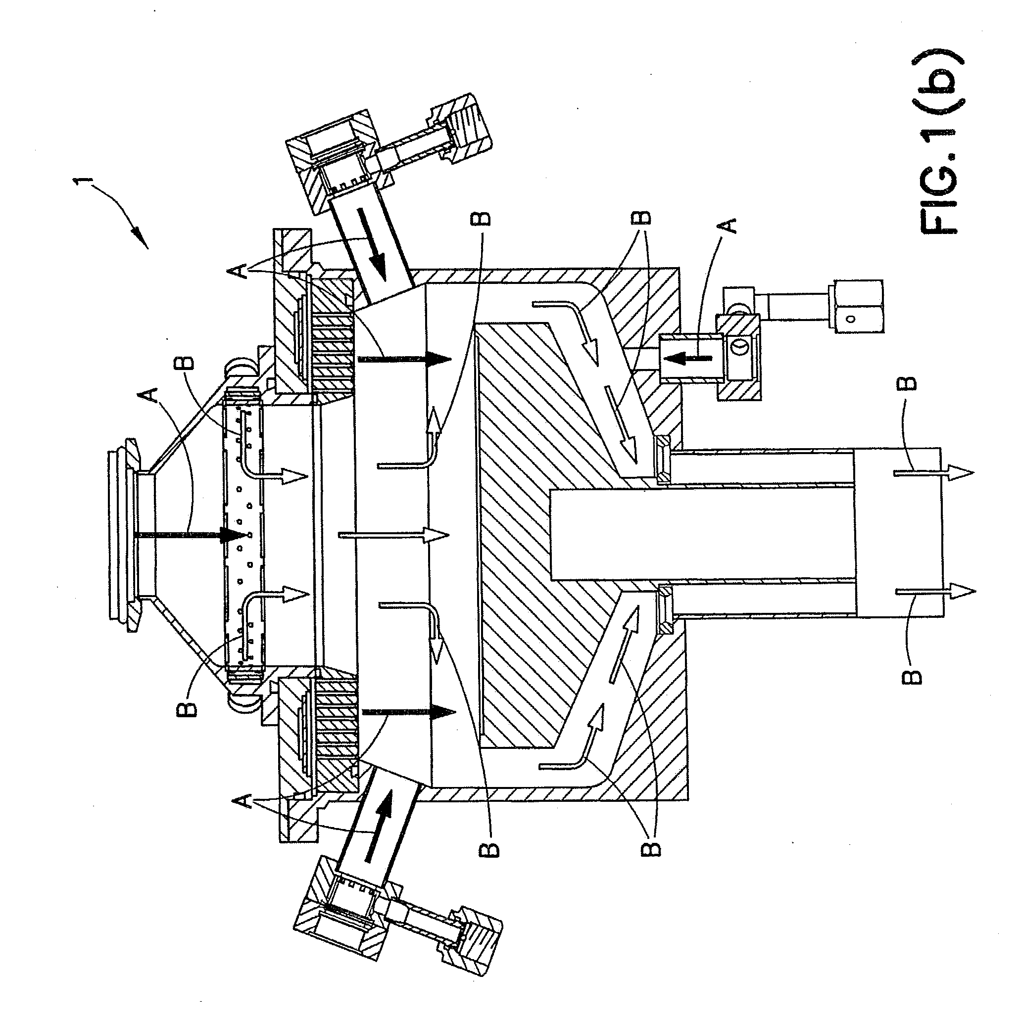
[0051]The present invention is directed to an atomic layer deposition apparatus 1 and system, as illustrated in one preferred and non-limiting embodiment in FIGS. 1(a)-1(e). In particular, and in this embodiment, the ato...


PUM

PropertyMeasurementUnit
Thicknessaaaaaaaaaa
Pressureaaaaaaaaaa
Flow rateaaaaaaaaaa

Abstract

An atomic layer deposition apparatus, including: a chamber with an internal volume; a fixture assembly to hold a substrate within the internal volume of the chamber; a plurality of gas injection ports to facilitate the introduction of gas; at least one precursor gas arrangement to introduce precursor gas into the internal volume; and at least one inactive gas dispersion arrangement to introduce inactive gas into the internal volume. The inactive gas dispersion arrangement is in the form of a primary dispersion member configured to concentrically focus the precursor gas towards a surface of the substrate. A modeling system for an atomic layer deposition apparatus is also disclosed.

Description

CROSS REFERENCE TO RELATED APPLICATIONS[0001]This application claims benefit of priority from U.S. Provisional Patent Application No. 61 / 517,554, filed Apr. 21, 2011, which is incorporated herein by reference in its entirety.BACKGROUND OF THE INVENTION[0002]1. Field of the Invention[0003]This invention relates generally to deposition systems and methods, and in particular to systems and methods for use in connection with atomic layer deposition processes, such as growing a thin film onto a substrate through plasma-enhanced atomic layer deposition (PEALD).[0004]2. Description of the Related Art[0005]As is known in the art of deposition technologies, atomic layer deposition (ALD) is a chemical vapor deposition (CVD) technique that enables surface-controlled film growth on the atomic scale with excellent uniformity. Surface-controlled film growth is a unique feature that is based on sequential, self-limiting chemical reactions between gas-phase precursor molecules and active surface sp...

Claims


Application Information

Patent Timeline
IPC IPC(8): C23C16/455C23C16/513C23C16/52C23C16/458
CPCC23C16/452C23C16/45544C23C16/45536C23C16/45519C23C16/45504C23C16/45517C23C16/45523C23C16/45525C23C16/45557C23C16/45565C23C16/45574C23C16/4558C23C16/52H01J37/32449
Inventor RAYNER, JR., GILBERT BRUCE
Owner KURT J LESKER
Learn More