Eureka AIR delivers breakthrough ideas for toughest innovation challenges, trusted by R&D personnel around the world.

Melting method and apparatus

Inactive Publication Date: 2012-11-01
PAULI ROGER
View PDF6 Cites 4 Cited by
  • Summary
  • Abstract
  • Description
  • Claims
  • Application Information

AI Technical Summary

Benefits of technology

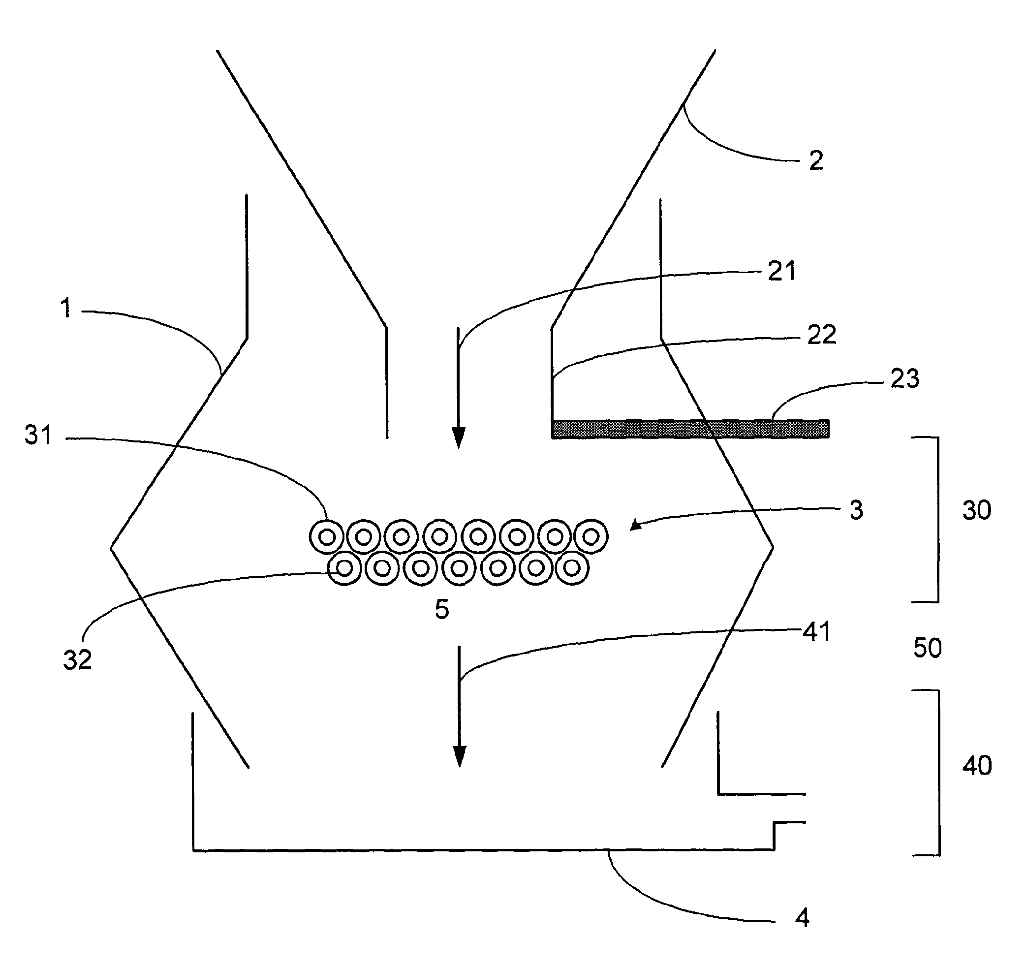
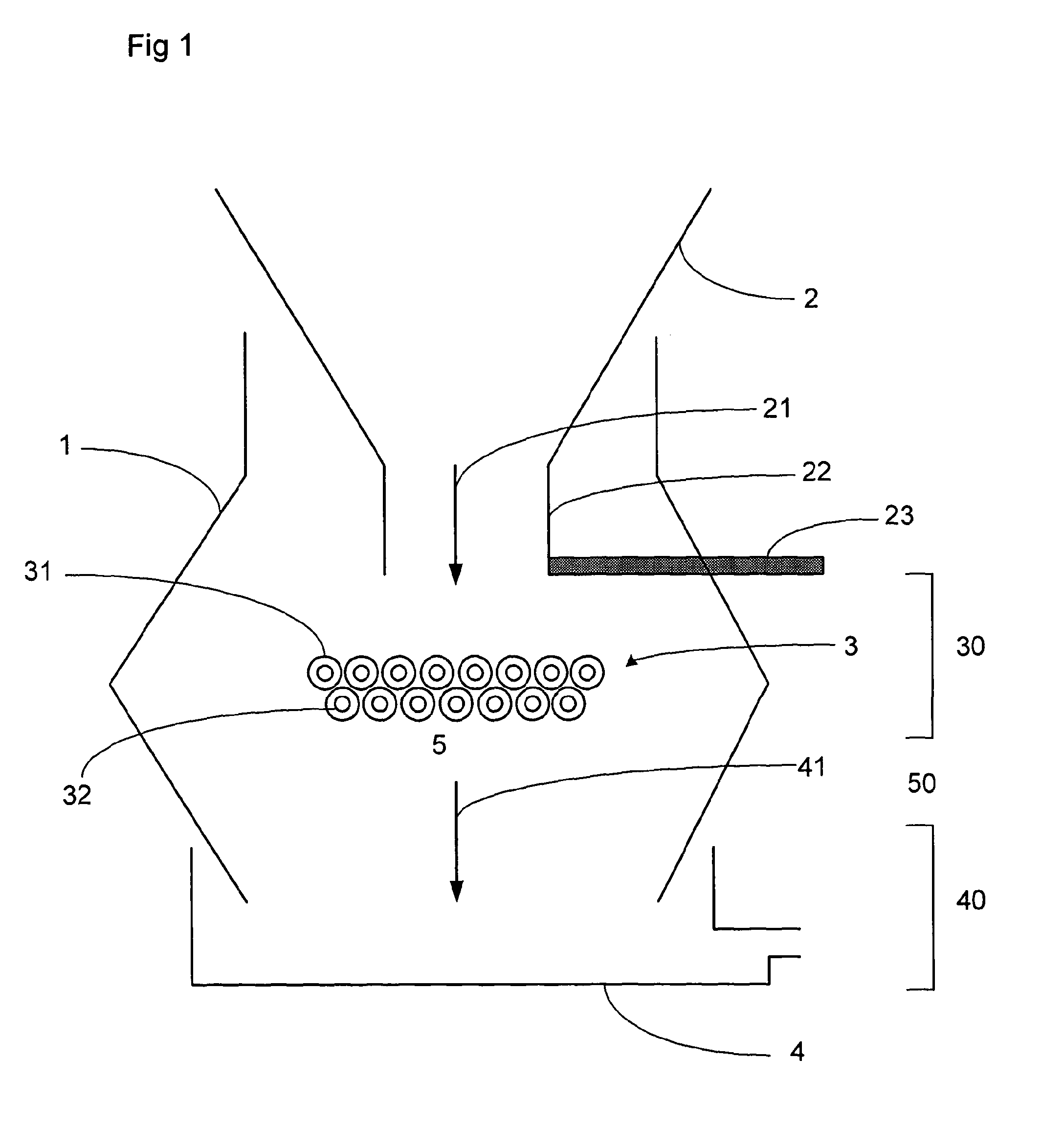
[0015]A further advantage of the present invention is that it minimises contact between the melted raw material and the melting chamber walls. This helps to keep contamination from the chamber walls to a minimum. The reduced risk of contamination in turn enables a greater variety of different materials to be available for use as the chamber walls.
[0016]In the case of glass processing, the phase separation barrier of the invention provides a large contact area with the raw material as it melts, which aids the mixing of the glass batch constituents and the removal of gaseous inclusions from the melted glass.
[0017]In a particular embodiment of the invention, the heating element is separated from, i.e. not in contact with, the melted material which is collected at the base of the chamber. Thus, there is a gap, typically an air gap, between a melting zone containing the phase separation barrier and a collecting zone in which melted raw material is collected. Melted raw material accordingly falls through this gap following melting and before being collected at the base of the chamber. This has the benefit that any gases dissolved in the melt are encouraged to escape into the air as they fall from the phase separation barrier to be collected at the base of the chamber. The air gap therefore also aids removal of gaseous inclusions.
[0018]A particularly preferred embodiment of the invention employs a phase separation barrier of an inert, high melting temperature material such as fused quartz or iridium. These materials are inert in that they barely react on contact with vitreous glass and can be heated to temperatures in excess of 1550° C. Fused quartz is stable up to 1600° C., whilst iridium melts in the region of well above 2000° C. The use of phase separation barriers made of such materials enables very high temperature melting to be carried out without causing reaction with the melted glass. The increased temperature further speeds up the rate of the melting process.
[0019]The use of such high temperature melting also provides the skilled person with greater flexibility as to the type of glass which can be processed. Typically, metal oxides are added to the glass batch in order to reduce the melting temperature. However, where the melting temperature is increased to 1550° C. or more, e.g. by use of fused quartz or iridium as the phase separation barrier, the use of metal oxide salts can be reduced or even eliminated. The silica content of the glass can therefore be as high as 85%, and when using iridium phase separation barriers as high as 90%.
[0020]A further advantage of the use of fused quartz phase separation barriers is provided by its minimal thermal expansion (typically 0.5×10⁻⁶K−1). This gives the phase separation barrier a very high thermal shock resistance, thus allowing rapid heating and charging of raw material such as glass batch into the melting chamber. The high resistance to thermal shock means that, unlike conventional melting furnaces, there is no requirement for controlled heat up of the chamber before the melting process begins. This makes the use of the process of the invention appropriate for both batch and continuous melting processes and provides flexibility with regard to the melting of speciality materials where continuous processes are inefficient. It also simplifies the process of changing the melt composition.

Problems solved by technology

In particular, the melting process can be very slow.
In the case of glass, the molten pool of material insulates the newly added solid glass batch from the heat source leading to a particularly slow and inefficient melting process.
However, many glass melting chambers still employ a heat transfer mechanism to melt or aid the melting of the glass batch.
A further problem with conventional melting processes is the long residency time which is required.
This mixing through convention currents means that a long residency time is required to ensure complete melting and homogenisation of the glass.
A further difficulty with currently used melting chambers is the need to run the process continuously.
Conventional chambers cannot be rapidly heated and cooled due to the difficulties of thermal shock and it is therefore necessary to employ controlled heating and cooling.
However, in the case of speciality materials where a continuous process is undesirable, the inefficient controlled heating and cooling steps cannot be avoided.
A particular problem associated with the melting of glass relates to the presence of bubbles in the melted glass batch.
Glass melts may also suffer from contamination through contact with the chamber walls in currently used melting furnaces.
This leads to an increased likelihood of contamination on contact with the walls.
It has been proposed to use noble metals to form the chamber walls to avoid such contamination, but at the high temperatures in the melting chamber some chamber damage or contamination even with these materials may occur.
Typical glass melting chambers operate at a temperature in the region of 1450° C. Higher temperatures are difficult to achieve, particularly given the insulation effect of the glass melt and the chamber / refractory materials.
The limitations of the temperature of operation of the melting furnaces currently in use therefore impose undesired limitations on the composition of glass which can be produced.

Method used


Image

  • Melting method and apparatus
  • Melting method and apparatus
  • Melting method and apparatus

Examples


example a

First Melting Chamber:

[0082]Raw material: 75 wt % silica, 25 wt % sodium carbonate, total weight 200 g

Phase separation barrier heated to: 1,600° C.

Second Melting Chamber:

[0083]Raw material: intensely coloured glass in an amount of up to 20 g

Phase separation barrier heated to: 1450° C.

example b

First Melting Chamber:

[0084]Raw material: 75 wt % silica, 25 wt % sodium carbonate, total weight 200 g

Phase separation barrier heated to: 1,600° C.

Second Melting Chamber:

[0085]Raw material: non-coloured, high Pb content glass having a PbO content of up to 92 wt %

Phase separation barrier heated to: 950° C.

[0086]The two melts are combined in a homogeniser chamber. This example is a batchwise process in which the entire melt from each chamber is discharged into the homogeniser chamber. In a continuous process, the two melts are combined at an appropriate ratio, e.g. first melt: second melt weight ratio of from about 2:1 to about 10:1, e.g. about 5.1.

[0087]A further embodiment of the invention is depicted schematically in FIG. 6. In this embodiment, the apparatus incorporates a first homogeniser chamber 103 and a second homogeniser chamber 113. The first melting chamber 101, which is used to melt the major component of the final product (typically silica) is connected to both the first ...

example 1

[0089]A single silicon carbide (SiC) resistance heating element was placed inside a silica tube, with a total heated length of 200 mm and a diameter of 30 mm. Power was applied and the external temperature of the tube reached 1000° C. in five minutes. The silica tube showed no signs of thermal shock or cracking as a result of the rapid heating rate employed.


PUM

PropertyMeasurementUnit
Temperatureaaaaaaaaaa

Abstract

A method and apparatus for melting a raw material such as glass. The method comprises a creating a flow of raw material interrupted by a heated phase separation barrier (3,31,32), wherein melting is achieved by transfer of heat from the phase separation barrier to the raw material. The process comprises: providing solid raw material to the phase separation barrier, wherein the phase separation barrier supports the solid raw material; heating the phase separation barrier to a temperature which is (a) at least 700° C. and (b) sufficient to cause melting of the solid raw material which contacts the barrier, wherein any melted raw material formed on contact with the phase separation barrier flows off or through the phase separation barrier; and collecting the melted raw material; wherein the phase separation barrier causes separation of the solid and melted phases within the flow of the raw material. Two or more melters may be used in parallel and the resultant melted raw materials mixed together in the melted state. In addition, there is provided a method and apparatus for producing a melt comprising a mixture of melted raw materials. The apparatus comprises two melting chambers connected via outlets to a homogeniser.

Description

FIELD OF THE INVENTION[0001]The invention relates to methods of melting a raw material such as glass, and apparatus for use in such melting processes.BACKGROUND TO THE INVENTION[0002]The processing of raw materials such as glass or metals typically involves a high temperature melting step in which a solid raw material such as glass batch is melted to form a molten pool which can then be further processed or refined. Melting is typically carried out in a melting chamber by use of a continuous process. The melting chamber contains a pool of molten material to which additional solid material is added. The chamber is heated, for example by heating the chamber walls, by reflection from the crown of the furnace, or by other external heat source, to effect melting of the solid raw material.[0003]This conventional melting process has a number of draw-backs. In particular, the melting process can be very slow. In the case of glass, the molten pool of material insulates the newly added solid ...

Claims


Application Information

Patent Timeline
IPC IPC(8): C03B3/02C03B5/225
CPCC03B3/02C03B5/0336C03B5/1675C03B5/1672C03B5/04C03B5/235
Inventor PAULI, ROGER
Owner PAULI ROGER
Why Eureka
Eureka Blog
Learn More