Internal Faraday Shield Having Distributed Chevron Patterns and Correlated Positioning Relative to External Inner and Outer TCP Coil

a technology of chevron patterns and faraday shields, applied in the direction of magnetic/electric field screening, electric discharge tubes, electrical equipment, etc., can solve the problems of adversely affecting wafer throughput interfering with the etching process, etc., and achieves less time for equipment cleaning operations and high throughput.

a technology of chevron patterns and faraday shields, applied in the direction of magnetic/electric field screening, electric discharge tubes, electrical equipment, etc., can solve the problems of adversely affecting wafer throughput interfering with the etching process, etc., and achieves less time for equipment cleaning operations and high throughput.

US20120273130A1Active Publication Date: 2012-11-01LAM RES CORP

Image

  • Internal Faraday Shield Having Distributed Chevron Patterns and Correlated Positioning Relative to External Inner and Outer TCP Coil
  • Internal Faraday Shield Having Distributed Chevron Patterns and Correlated Positioning Relative to External Inner and Outer TCP Coil
  • Internal Faraday Shield Having Distributed Chevron Patterns and Correlated Positioning Relative to External Inner and Outer TCP Coil

Examples


Embodiment Construction

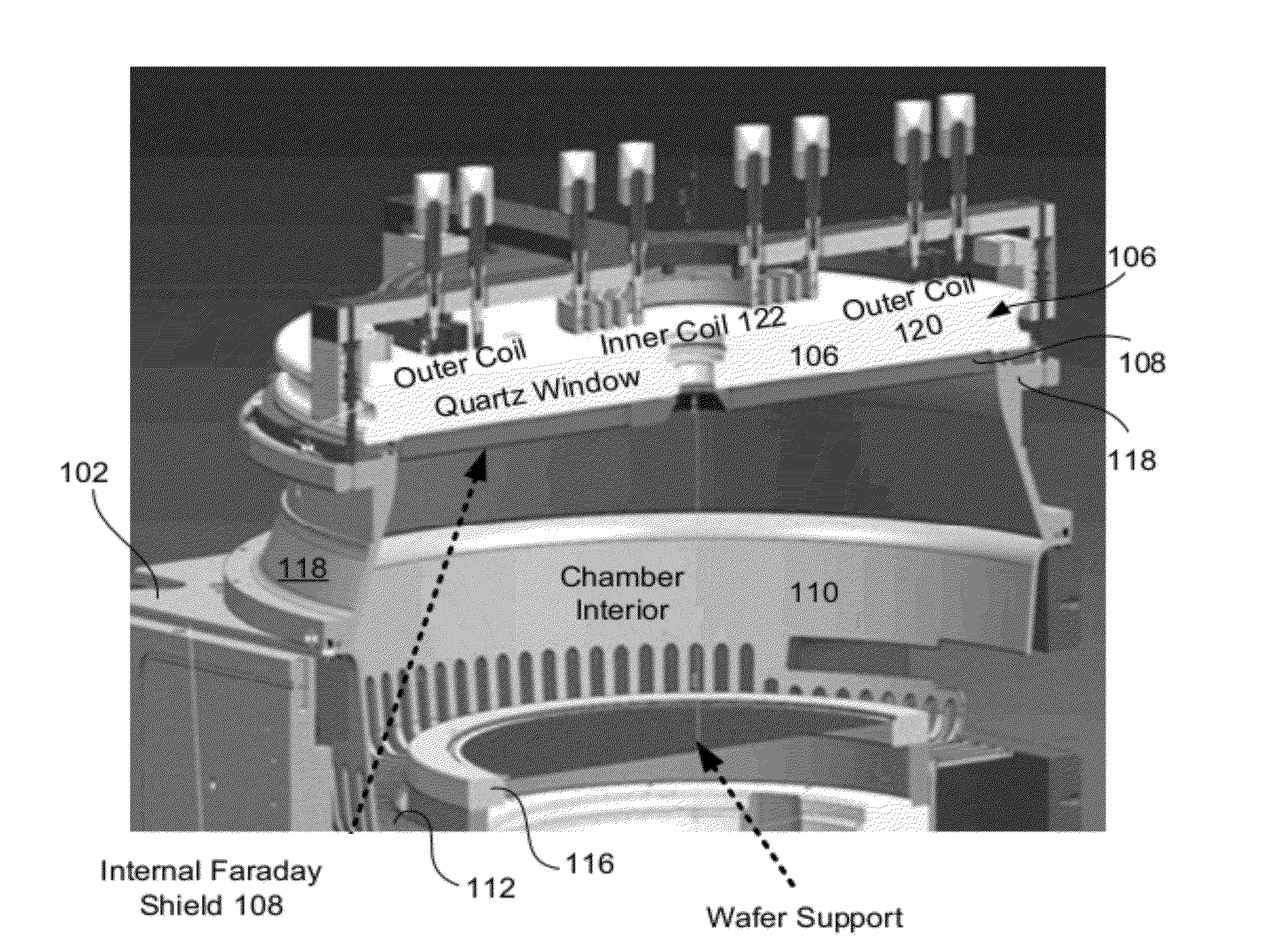
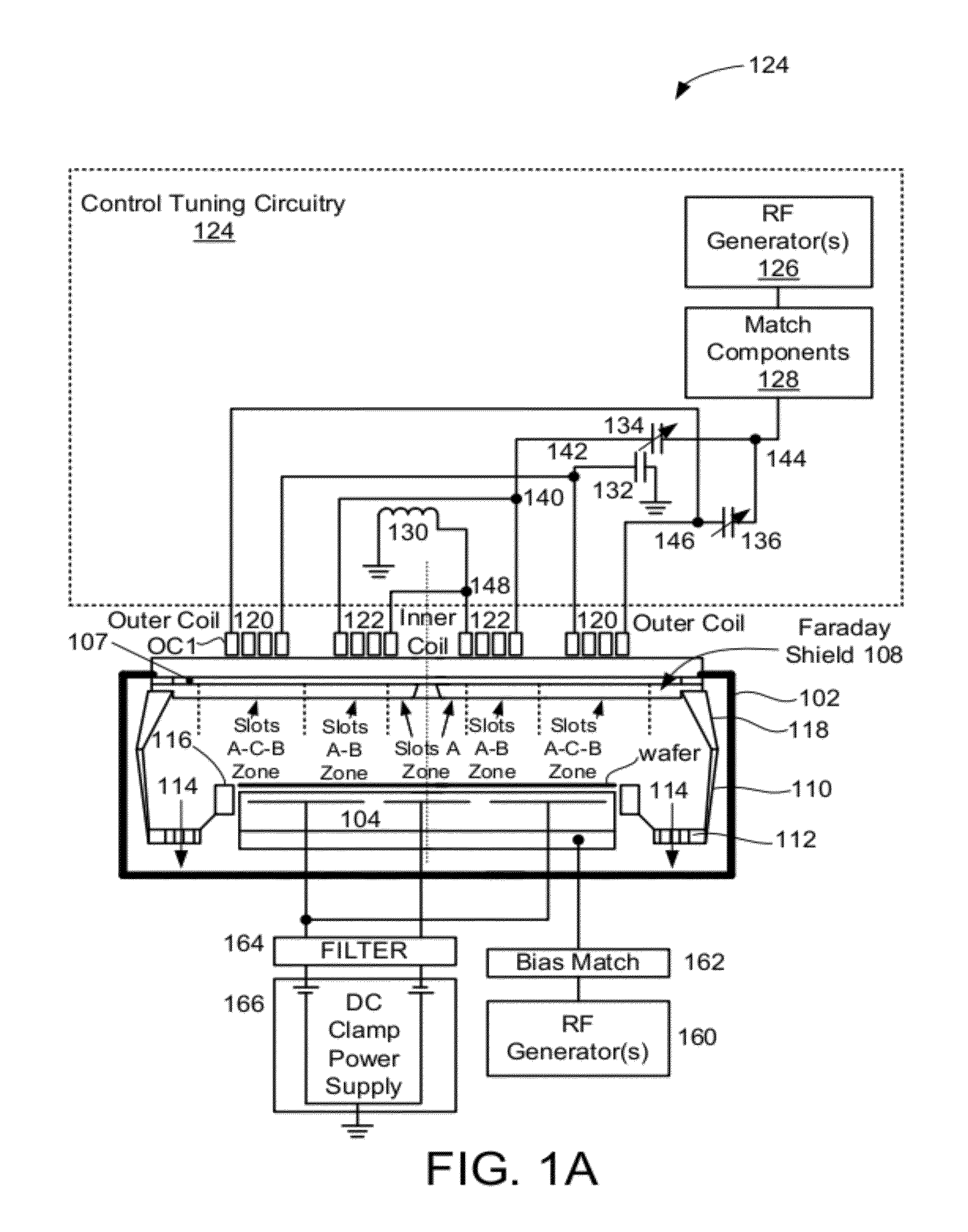
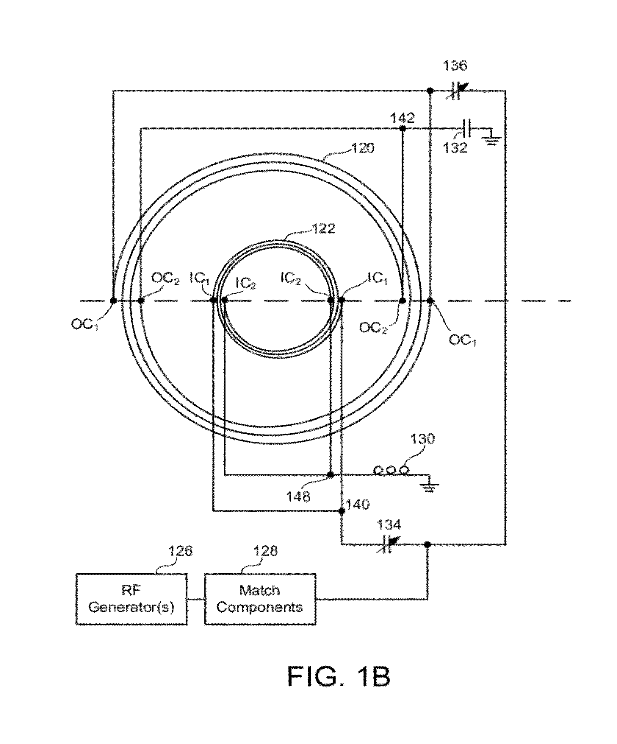
[0037]Disclosed is an apparatus used in etching semiconductor substrates and layers formed thereon during the manufacture of semiconductor devices. The apparatus is defined by a chamber in which etching is performed. A Faraday shield is disposed within the chamber, and is configured with a three zone slot configuration that is correlated to the placement of a TCP coil disposed over a dielectric window of the chamber. In the following description, numerous specific details are set forth in order to provide a thorough understanding of the present invention. However, it will be apparent to one skilled in the art that the present invention may be practiced without some of these specific details. In other instances, well known process operations and implementation details have not been described in detail in order to avoid unnecessarily obscuring the invention.

[0038]In an inductively coupled plasma etch module comprising a planar window and a generally planar excitation coil, adapted for...


PUM

PropertyMeasurementUnit
Lengthaaaaaaaaaa
Lengthaaaaaaaaaa
Lengthaaaaaaaaaa

Abstract

Plasma processing chambers having internal Faraday shields with defined groove configurations, are defined. In one example, the chamber includes an electrostatic chuck for receiving a substrate and a dielectric window connected to a top portion of the chamber, where the dielectric window disposed over the electrostatic chuck. Also included is a Faraday shield disposed inside of the chamber and defined between the electrostatic chuck and the dielectric window. The Faraday shield includes an inner zone having an inner radius range, a middle zone having a middle radius range, an outer zone having an outer radius range, where the inner zone is adjacent to the middle zone, and the middle zone being adjacent to the outer zone. Further defining the Faraday shield is a first set of radial slots (A) extending through the inner zone, the middle zone, and the outer zone, a second set of radial slots (C) extending through only the outer zone; and a third set of radial slots (B) extending through the middle zone and outer zone. In this configuration, the first, second and third radial slots are arranged radially around the Faraday shield in a repeating pattern of slots A, C, B, and C.

Description

PRIORITY CLAIM[0001]This application claims priority from U.S. Provisional Patent Application No. 61 / 480,314 filed on Apr. 28, 2011 and entitled “Internal Faraday Shield Having Distributed Chevron Patterns and Correlated Positioning Relative to External Inner and outer TCP Coil,” which is incorporated herein by reference in its entirety for all purposes.FIELD OF THE INVENTION[0002]The present invention relates generally to semiconductor fabrication, and more particularly, to an apparatus containing a Faraday shield for maintaining the condition of a window of an inductively coupled plasma etching apparatus.DESCRIPTION OF THE RELATED ART[0003]In semiconductor manufacturing, etching processes are commonly and repeatedly carried out. As is well known to those skilled in the art, there are two types of etching processes: wet etching and dry etching. One type of dry etching is plasma etching performed using an inductively coupled plasma etching apparatus.[0004]A plasma contains various t...

Claims


Application Information

Patent Timeline
01 Nov 2012
Publication
US20120273130A1
IPC
H01L21/3065; H05K9/00
CPC
H01J37/32651; C23F1/00; H01L21/3065; H01J37/321; H01J37/32633
Inventors
DREWERY, JOHN; LONG, MAOLIN