However, the
wafer polishing and surface activation processes could cause the interconnect vias interface surface to be recessed below the
dielectric surface which would result in the presence of a gap between the opposing vias across the
wafer bonding interface surface.
The presence of such gaps between the interconnect vias could cause excessive level of electrical resistance between the corresponding electrical circuits of the bonding wafers.
When the
thermal expansion characteristics of the two wafers to be bonded are substantially different, excessive and prolonged elevated temperature annealing after the bonding intermediary
layers of the respective wafers have been fused together as described in U.S. Pat. Nos. 7,622,324, 7,553,744, 7,485,968 and 7,387,944 would be terminal to the bonded wafers and would likely cause the achieved bonding to fail causing de-bonding of the intermediary
layers.
This means that the prior art prior art bonding methods (see U.S. Pat. Nos. 7,622,324, 7,553,744, 7,485,968 and 7,387,944) are not likely to be effective in the bonding of wafers having substantially dissimilar
thermal expansion characteristics such as the case when a wafer made from III-V material needs to be bonded to a Si wafer such as described in U.S. Pat. Nos. 7,623,560, 7,767,479 and 7,829,902.
No prior art was found that describes
wafer bonding that incorporates means of the bonding of multiple wafers that incorporate means for the transfer of light signals between the bonded wafers.
However, when the
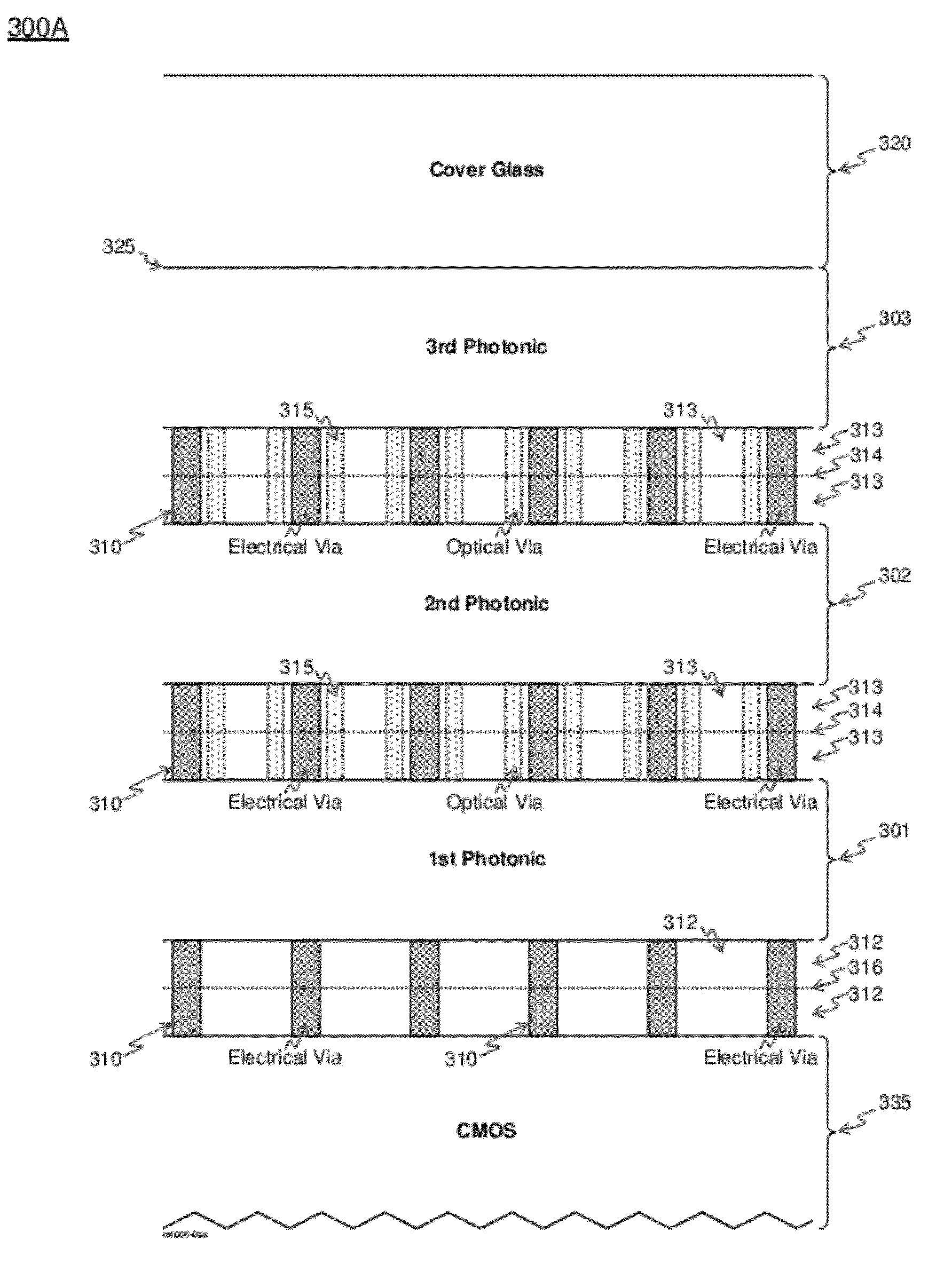
wafer bonding surface needs to transfer light in addition to electrical signals the situation becomes vastly different since the excessive height of the interconnect vias would consequently cause excessive thickness of the intermediary bonding layer between the two wafers which could cause undesired attenuation (through absorption) of the light being transferred between the bonded wafers (
layers) especially since the
resultant thickness of the bonding between the two wafers is double the thickness of the intermediary bonding layers formed at the bonding side of each of the two wafers.
No prior art exists that describes methods for
wafer bonding at such ultra high interconnect density especially incorporating means for the transfer of both light and electrical signals transfer between the bonded wafers across the bonding layer.
Therefore, prior art wafer bonding methods (see U.S. Pat. Nos. 7,622,324, 7,553,744, 7,485,968 and 7,387,944) in which the
diameter of the
electrical interconnect vias as a design parameter, and consequently the achievable density of the interconnect vias, do not take into account the limitation such a parameter places on the pixel
pitch that can be achieved when such wafer bonding methods are used in the bonding of the
semiconductor wafers of ultra high optical element (pixel) density
optoelectronics devices such as those described in U.S. Pat. Nos. 7,623,560, 7,767,479 and 7,829,902.
The limitation of the existing prior art (see U.S. Pat. Nos. 7,622,324, 7,553,744, 7,485,968 and 7,387,944 and M. Alexe and U. Güsele,
Wafer Bonding Applications and Technology, pp 327-415, Springer 2004 and Q. Y. Tong and U. Güsele,
Semiconductor Wafer Bonding Science and Technology, pp 203-261, Wiley 1999) is that at such a fine via
pitch the amount of
metal in the formed
fine pitch interconnect via would not be sufficient to close the gap between the vias using post bonding elevated temperature annealing unless the via height and
diameter, and consequently the intermediary bonding layers thickness is substantially increased to become significantly larger than 1.5 micron, which would result in interconnect vias having a fairly high
aspect ratio (expressed in terms of the ratio of the via height to its
diameter).
As explained earlier, such an increase in the intermediary bonding
layer thickness will become even more detrimental to the transfer of light signals between the bonded wafers for the case when light has to be transferred across the bonding interface.
Furthermore, when the interconnect vias
aspect ratio becomes too high, the expansion of the interconnect vias during the elevated temperature annealing step required to interfuse the interconnect vias across the wafer bonding surface could result in the creation of gaps along the interconnect via height that ultimately be detrimental to achieving the low electrical resistance critically needed to transfer electrical
signal between the bonded layers.
Due to the ultra high
pixel density sought after in U.S. Pat. Nos. 7,623,560, 7,767,479 and 7,829,902 and the
resultant ultra high interconnect density, which can be higher than 4×10⁶ / m2, bonding techniques such as flip-
chip, conventional
eutectic bonding and the like are not a feasible way to realize multi-color emissive micro-
display device described in U.S. Pat. Nos. 7,623,560, 7,767,479 and 7,829,902.
In addition, the
electrical interconnect density that can be achieved by such wafer bonding techniques is limited to substantially less than one million electrical interconnects per
square centimeter.

