Integrated energy recovery systems

a technology of energy recovery and energy recovery, applied in the direction of lighting and heating equipment, process and machine control, instruments, etc., can solve the problems of small portion of a/c waste heat recovery, low domestic hot water consumption, etc., and achieve the effect of reducing waste heat, high water consumption, and material reduction of air conditioning electrical consumption

Inactive Publication Date: 2012-11-22
GOLDBERG MICHAEL
View PDF5 Cites 20 Cited by
  • Summary
  • Abstract
  • Description
  • Claims
  • Application Information

AI Technical Summary

Benefits of technology

[0006]In accordance with the present invention and in fulfillment of the foregoing object, the improved heat recovery system takes advantage of two key factors; compatible energy consumption and temperature in the separate processes, and very high water consumption. One function of the disclosed systems is recovery of waste heat from

Problems solved by technology

Energy cost and availability are currently forefront issues well known to all.
While heat recovery is an elegant way to reduce energy consumption, it can only work where the waste heat is discharged at sufficient temperature to be useful.
However, their domestic hot water consumption is low, and only a small portion of the A/C waste heat is recovered.
This is unfortunately often the case.
The key processes that discharge and employ waste heat occur at temperatures that are co

Method used


Image

  • Integrated energy recovery systems
  • Integrated energy recovery systems
  • Integrated energy recovery systems

Examples


Embodiment Construction

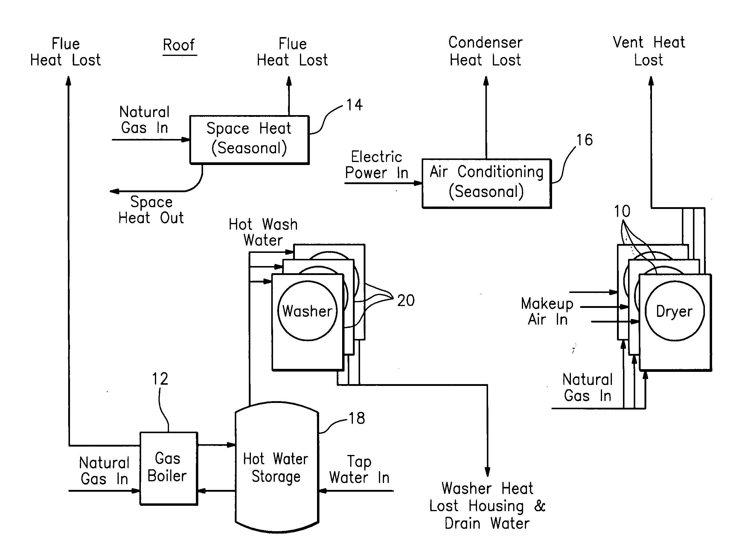
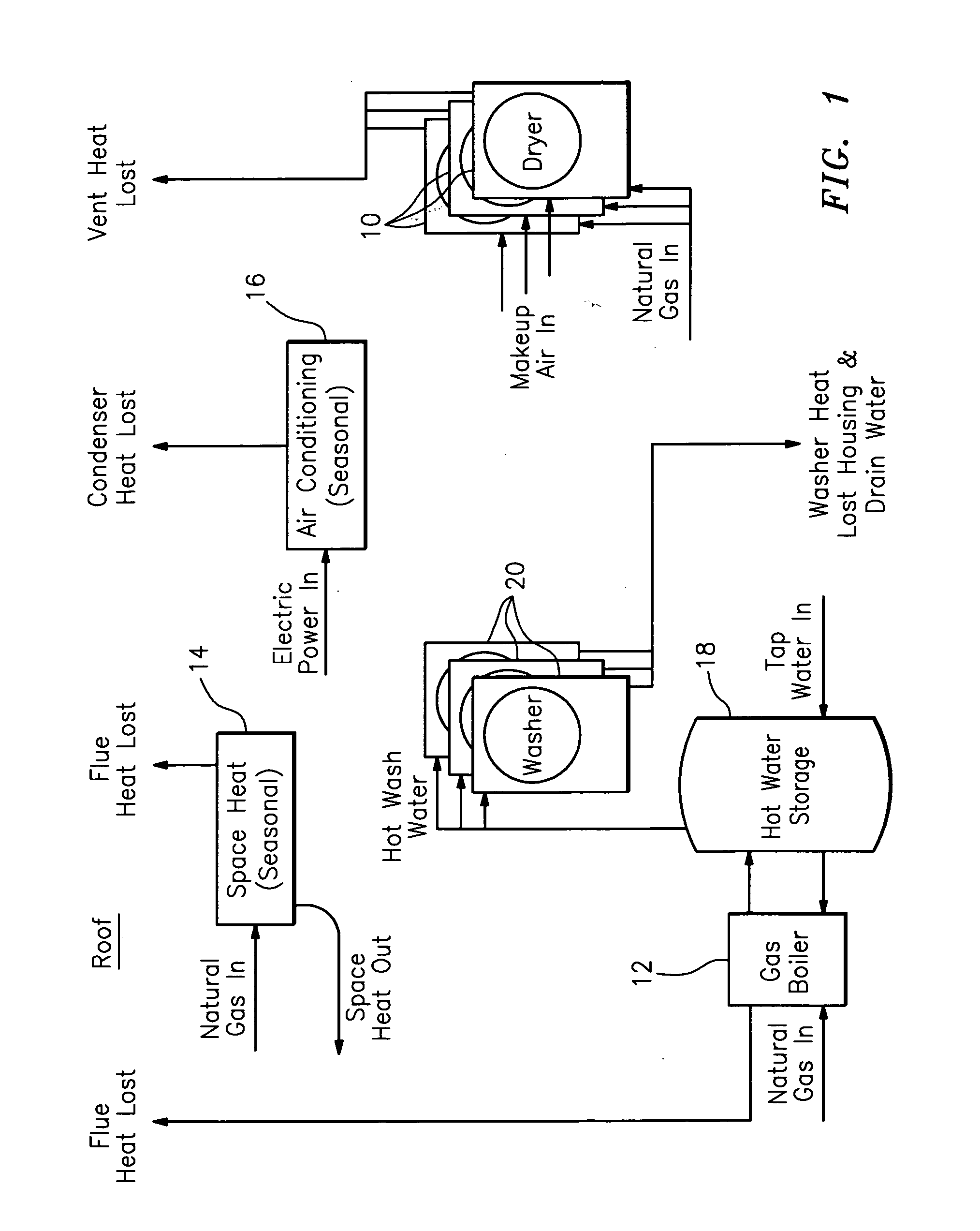
[0018]In a typical commercial laundry of the vended type as shown in FIG. 1, the key energy consuming processes are the dryers 10,10, washers 20,20 hot water boiler 12, the facility space heating system 14, and the facility air conditioning system 16. Each of these processes consumes significant energy, and discharges waste heat to the atmosphere and / or down the drain. Laundries generally employ a boiler that consumes fuel, typically natural gas or oil, and heats water, which is then stored in a separate tank as at 18. The washers 20, 20 draw on the tank as needed, and when each cycle is completed, the water is discharged, still substantially hot, down the drain. The dryers 10,10 draw ambient air, and consume substantial energy to heat the air to very high temperatures, ranging from 325 F. for 30 lb. dryers, to 550 F. for larger machines. This energy is most commonly supplied as natural gas, although propane and oil fired dryers, as well as electric and steam heated dryers are also ...


PUM


Abstract

An energy efficient laundry facility comprises a space heating system, an air conditioning system, a plurality of clothes washers, a plurality of clothes dryers, a hot water storage tank supplying the washers, a source of cold water and conduit means interconnecting the aforesaid. Dedicated heat recovery units are associated respectively with the dryers and employ high temperature dryer exhaust air to heat water for supply to the storage tank. A controller and temperature sensing means regulate the flow of hot water from the dryers to the storage tank. High temperature water is directed to the top of the storage tank and lower temperature water to an intermediate point in the storage tank. Hot water from the dryers is also directed to the space heating system. Each heat recovery unit comprises a heat exchanger, a blower, a water circulation pump, a water temperature sensor, and a dedicated controller. The controller may also include a dryer exhaust pressure monitor, a pressure controller, and a variable speed blower drive. The heat exchanger is of the counterflow type and each recovery unit has its heat exchanger and blower arranged to provide for right angle air flow resulting in a compact unit for mounting atop a clothes dryer. Hot water may also be drawn from the storage tank for use in either an air or hydronic space heating system.

Description

REFERENCE TO RELATED APPLICATION[0001]Reference is had to Provisional Patent Application entitled Integrated Energy Recovery Systems, inventor Michael Goldberg, filed Jun. 18, 2009, hereby incorporated herein by reference.BACKGROUND OF THE INVENTION[0002]Energy cost and availability are currently forefront issues well known to all. Research and investment are focused intensely on many facets of this dilemma, and much is being accomplished. In many industries, energy recovery is a key area of development. Typically, unused process heat that has historically been vented to the atmosphere or discharged into waterways, is now being captured. The captured heat may be used to preheat a target process and reduce energy consumption, or it may be used as the source heat for other processes in the same facility.[0003]While heat recovery is an elegant way to reduce energy consumption, it can only work where the waste heat is discharged at sufficient temperature to be useful. It is also essenti...

Claims


Application Information

Patent Timeline
IPC IPC(8): F28F27/00
CPCD06F39/006F28D21/0014D06F95/00D06F58/20
Inventor GOLDBERG, MICHAEL
Owner GOLDBERG MICHAEL
Why Eureka
Try Eureka