
Optical Sources

a technology of optical sources and pulses, applied in the field of optical sources, can solve the problems of adding complexity to the system, unable to provide optical pulses of sufficient power and frequency at the desired wavelength, or existing pulsed optical sources are optically very complex, and therefore expensive, so as to achieve tight focussing and integration, enhanced wavelength range and wavelength selection

Active Publication Date: 2012-11-22
NKT PHOTONICS
View PDF2 Cites 35 Cited by
  • Summary
  • Abstract
  • Description
  • Claims
  • Application Information

AI Technical Summary

Benefits of technology

The invention provides an optical source that uses seeded four-wave mixing to reduce noise and improve the efficiency of the process. The source includes a pump optical source, a seed signal forming apparatus, and a first microstructured optical fibre. The seed signal forming apparatus receives a seed pump signal and generates a seed signal at a different wavelength than the pump signal. The seed signal is then combined with the pump signal and sent through a second microstructured optical fibre to generate the output optical signal. The use of a second microstructured optical fibre allows for cascaded four-wave mixing and wavelength tuning. The technical effects of this invention include reduced noise, improved efficiency, and wavelength tuning.

Problems solved by technology

Many existing pulsed optical sources are either optically very complex, and therefore expensive, or are not able to provide optical pulses of sufficiently high power and frequency at the desired wavelengths.
However, these sources suffer the problem that the optimum pulse length for the laser system is much shorter (200-300 fs) than the optimum pulse length for STED (0.1-2 ns), and the pulses must therefore be stretched by a dispersive element, adding complexity to the system.
Furthermore, the output wavelength for Ti:Sapphire lasers is typically restricted to between approximately 700 nm and 1 um, meaning that the source cannot be used directly to deplete dyes requiring shorter wavelengths.
However, the complexity and cost of this approach can in many instances make it suitable only for laboratory research systems.
Although this approach gives high quality still images, its relatively low operating frequency (of the order of 1 MHz to a few MHz) means that it can typically not readily be adapted for use with high scanning speeds or video-rate imaging.
In addition, laser diodes are available at only a select number of wavelengths and these wavelengths do not always coincide with optimum excitation wavelengths of commercially available fluorescent dyes.
Providing multiple discrete laser systems results in a very complex and hence expensive instrument and a supercontinuum laser capable of generating an extremely high average power would be required in order to provide excitation beams of sufficient power for imaging applications.
However, the additional losses through a tuneable filter (AOTF for example) and launch into optical fibre, mean that the output spectral brightness of this source is significantly lower than a discrete laser diode, restricting use within high-end imaging systems.
Moreover, when interested in only a single wavelength at any time, supercontinuum lasers are relatively inefficient sources.

Method used


Image

  • Optical Sources
  • Optical Sources
  • Optical Sources

Examples


first embodiment

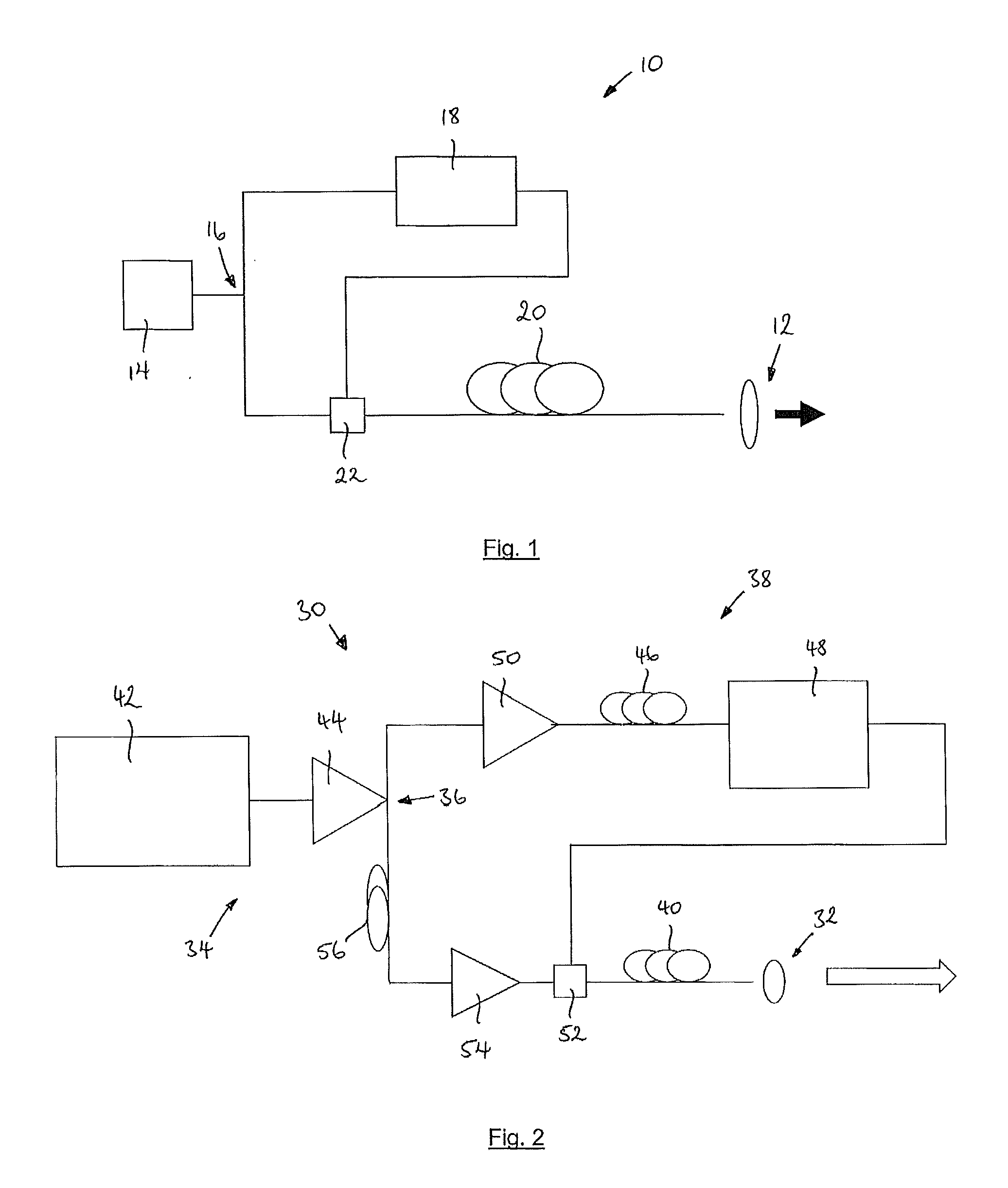
[0138]Referring to FIG. 1, the invention provides an optical source 10 comprising an optical output 12 arranged to output an output optical signal, a pump optical source 14, an optical splitter 16, seed signal forming apparatus 18 and a first microstructured optical fibre (MSF) 20.

[0139]The pump optical source 14 is arranged to generate an optical signal at a pump wavelength. The optical splitter 16 is arranged to receive the optical signal and to split the optical signal into a pump signal and a seed pump signal. The optical signal can comprise a pulsed or continuous wave (CW) optical signal, such that the optical source 10 can comprise a pulsed or CW optical source.

[0140]The seed signal forming apparatus 18 is arranged to receive the seed pump signal at the pump wavelength. The seed signal forming apparatus 18 is further arranged to transform the seed pump signal into a seed signal at a seed wavelength. The seed signal forming apparatus 18 comprises an optical element arranged to ...

second embodiment

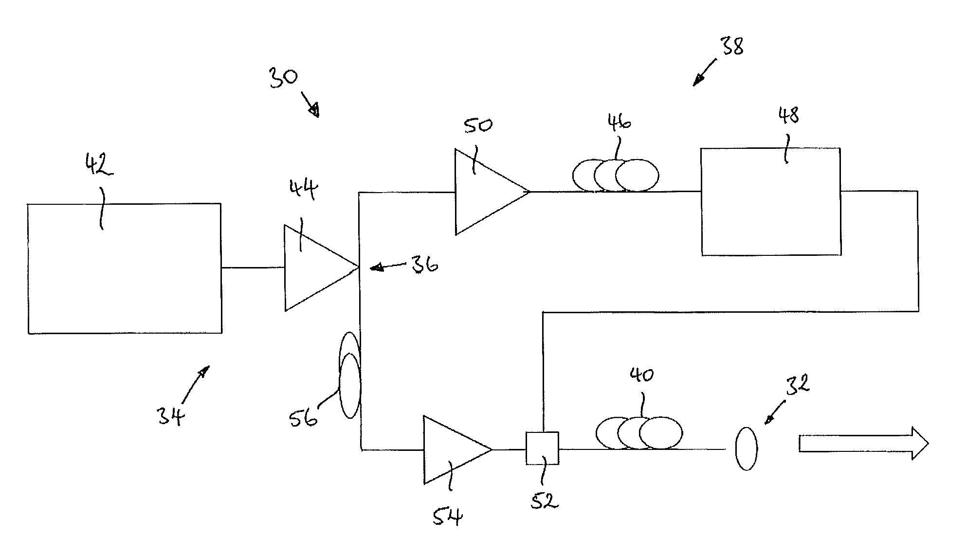
[0144]An optical source 30 according to the invention is shown in FIG. 2. The optical source 30 comprises an optical output 32 arranged to output an output optical signal, a pump optical source 34, an optical splitter 36, seed signal forming apparatus 38 and a first microstructured optical fibre (MSF1) 40.

[0145]The pump optical source 34 comprises a pulsed laser 42 arranged to generate an optical signal comprising optical pulses. The optical pulses have a pump wavelength of, in this example 1064 nm, a 20 MHz pulse frequency and a pulse duration of approximately 80 ps. The pump optical source 34 further comprises an optical amplifier 44 arranged to receive the optical pulses from the laser 42 and to amplify the pulses to have an average power in the region of 100 mW

[0146]The seed signal forming apparatus 38 comprises a first optical fibre 46 and an optical filter 48. A second optical amplifier 50 is provided between the optical splitter 36 and the seed signal forming apparatus 38, an...

third embodiment

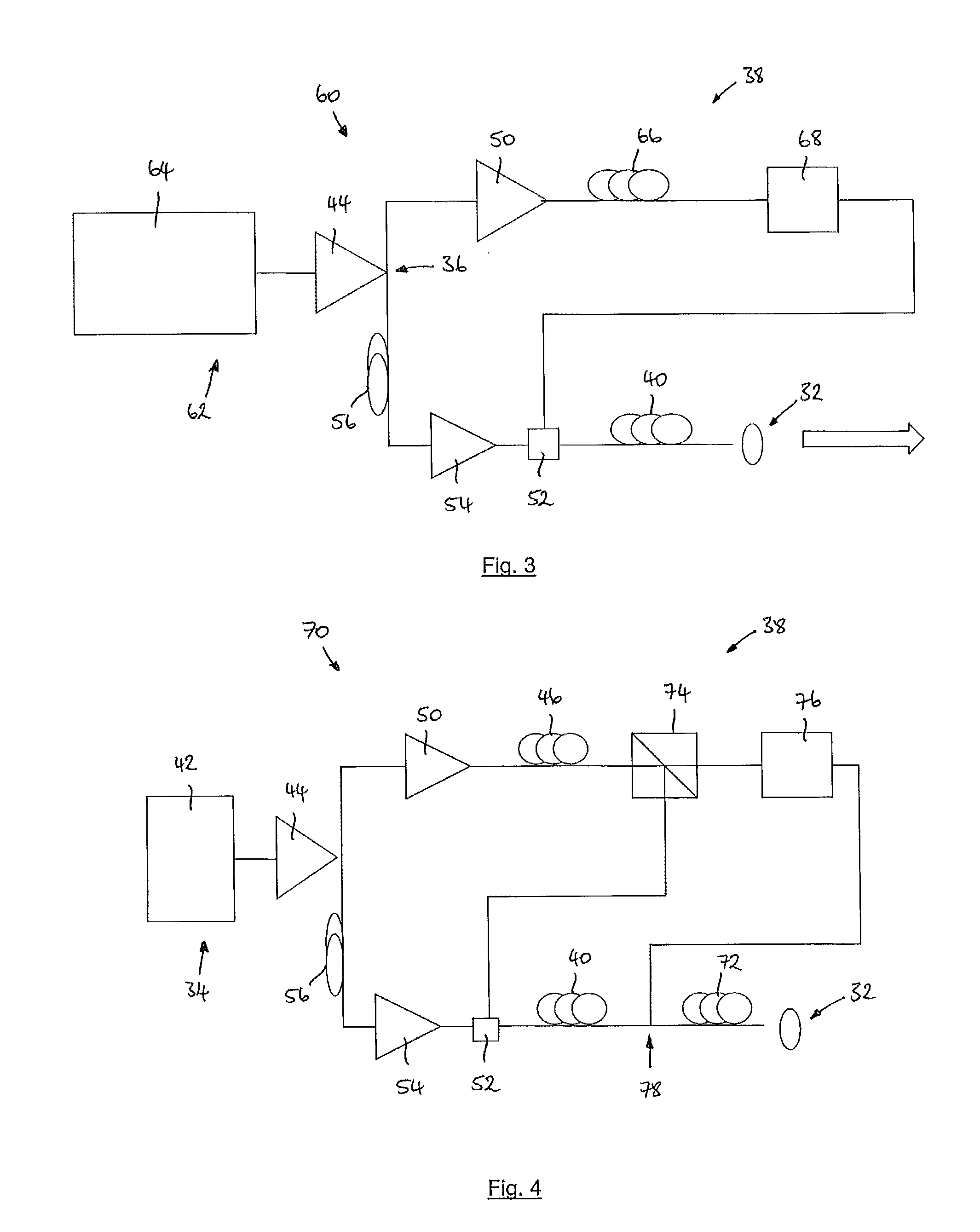
[0151]the invention provides an optical source 60, as shown in FIG. 3. The optical source 60 is substantially the same as the optical source 30 of the previous embodiment, with the following modifications. The same reference numbers are retained for corresponding features.

[0152]In this example, the pump optical source 62 comprises a wavelength tuneable pulse laser 64 operable to generate optical pulses at a pump wavelength tuneable between 1055 nm and 1080 nm. The optical pulses have a pulse frequency of 20 MHz, a pulse duration of 80 ps. The optical amplifier 44 is arranged to receive the pulses from the laser 64 and to amplify them to an average optical power of approximately 100 mW.

[0153]In this embodiment, the seed signal forming apparatus comprises a second microstructured optical fibre (MSF2) 66 of the same type and length as MSF140. MSF2 is arranged to receive the seed pump pulse and to cause the seed pump pulse to undergo four-wave mixing on transmission through the fibre 66...


PUM

PropertyMeasurementUnit
wavelengthaaaaaaaaaa

Abstract

An optical source (10) comprising an optical output (12), a pump optical source (14), an optical splitter arranged to receive an optical signal from the pump optical source and to split the optical signal into a pump signal and a seed pump signal. A seed signal forming apparatus (18) is arranged to receive the seed pump signal at the pump wavelength and to transform the seed pump signal into a seed signal at a seed wavelength. A first microstructured optical fibre (MSF1) (20) is arranged to receive the pump signal and the seed signal. MSF1 is arranged to cause the pump signal to undergo four-wave mixing seeded by the seed signal on transmission through MSF1 such that a first optical signal at a signal wavelength and second optical signal at an idler wavelength are generated. One of the signal wavelength and the idler wavelength are the seed wavelength and one of the first and second optical signals are provided to the optical output.

Description

FIELD OF THE INVENTION[0001]The invention can include many aspects, including methods and apparatus relating to optical sources, such as tuneable optical sources, suitable for a variety of applications, including applications as sources in fluorescence imaging apparatus, including flow cytometry apparatus and confocal and stimulated emission depletion (STED) microscopy apparatus. Aspects of the invention can also include methods and apparatus relating to the aforementioned fluorescent imaging apparatus, including flow cytometry apparatus, as well as confocal and STED microscopy apparatus.BACKGROUND TO THE INVENTION[0002]Many imaging applications, such as fluorescence imaging and stimulated emission depletion (STED) microscopy (first reported by S. Hell et al, “Breaking the diffraction resolution limit by stimulated emission: stimulated emission depletion microscopy”, Optics Letters, 19, 1994), can require high power, spatially coherent pulsed light sources operating in the UV, visib...

Claims


Application Information

Patent Timeline
Patent Type & Authority Applications(United States)
IPC IPC(8): G02F1/39G02F1/383G01J3/44G02F1/365G01J1/58
CPCG01N21/6458G02B21/0032G02B21/0076G02F1/3532G02F1/3536G02F2001/3507G02F2001/392G02F2202/32H01S3/005H01S3/067H01S3/06741H01S3/1618G02F1/395G02F2001/3528G02F1/3507G02F1/3528G02F1/392G01N21/65G01N2021/653G02B21/0084H01S3/0092H01S3/30
Inventor GRUDININ, ANATOLYCLOWES, JOHNDUPRIEZ, PASCALYARROW, MICHAEL
Owner NKT PHOTONICS
Learn More