Surface emitting laser diode, optical scanning apparatus and image forming apparatus
- Summary
- Abstract
- Description
- Claims
- Application Information
AI Technical Summary
Benefits of technology
Problems solved by technology
Method used
Image
Examples
first modified embodiment
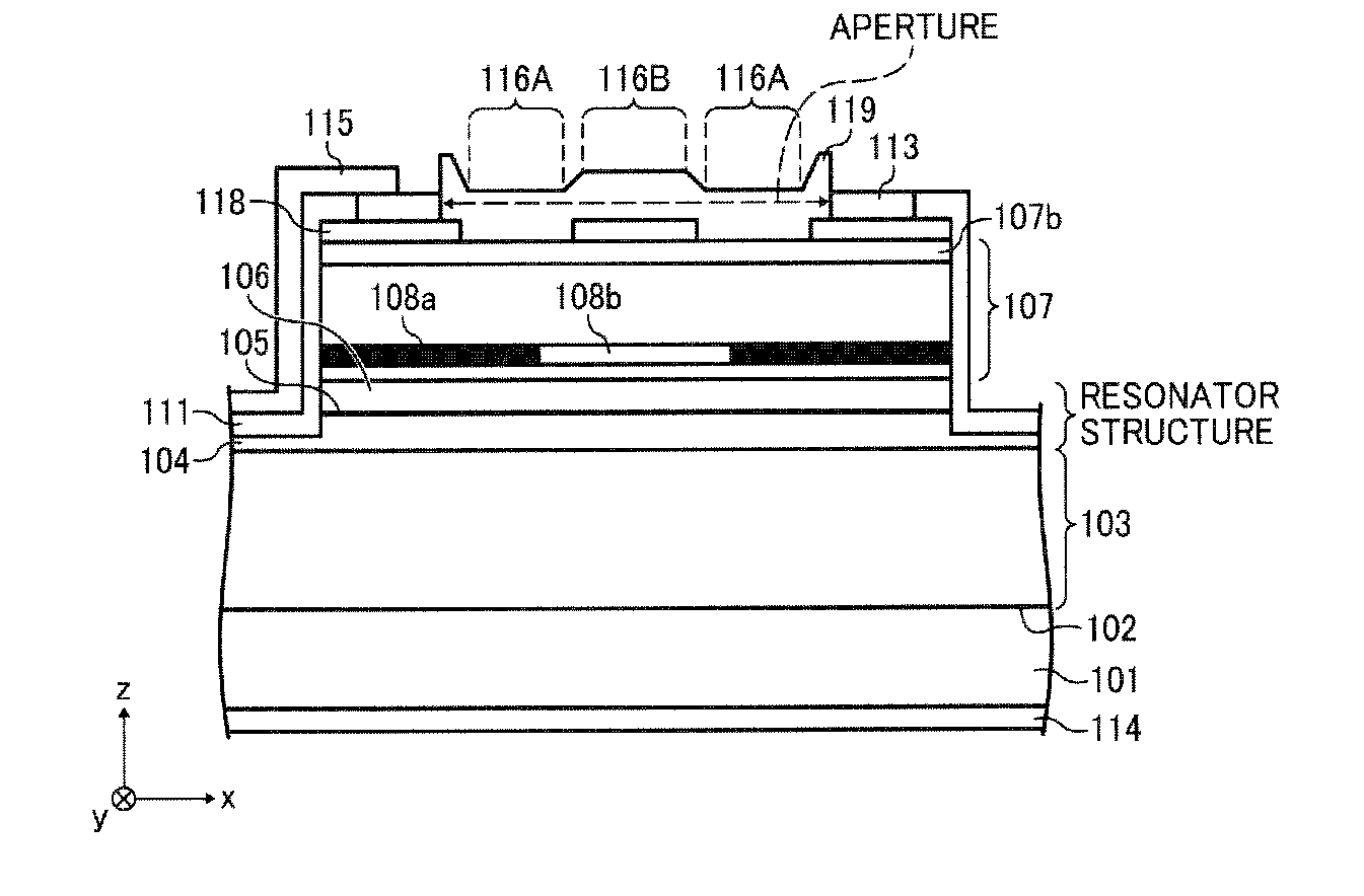
[0191]FIG. 37 shows first modified embodiment of surface emitting laser diode array. The upper semiconductor DBR 107 includes a low refractive index layer 107b existing in +z axis direction made of p-Al0.9Ga0.1As. A semiconductor layer 118 having larger refractive index than the low refractive index layer 107b is formed with an optical thickness of λ / 4 in +z axis direction. Further, the part of semiconductor layer 118 included in the emission region is removed by etching process. The part which the semiconductor layer 118 is removed corresponds to the semiconductor surface structure 116A and the center part which the semiconductor layer 118 is not removed corresponds to the semiconductor surface structure 116B.
[0192]In the first modified embodiment, the same effects may be realized as same as the surface emitting laser diode array 100.
second modified embodiment
[0193]FIG. 38 shows second modified embodiment of surface emitting laser diode array. In this embodiment, the emission region of the surface emitting laser diode array of the first modified embodiment is covered by a dielectric layer 119 having an optical thickness of 2λ / 4. For example, the layer 119 occupies the aperture in the upper electrode 113.
[0194]In the second modified embodiment, additionally, oxidation and pollution of the emission region may be prevented.
[0195]The dielectric layer 118 may be made of any one of SiN, SiO2, SiON, ZrO2, TiO2 and TiN. The dielectric layer 118 may be formed by plasma CVD, electron beam deposition, physical vapor deposition and relative sputtering.
[0196]The optical thickness of the dielectric layer 119 becomes even multiple of λ / 4.
third modified embodiment
[0197]FIG. 39 shows second modified embodiment of surface emitting laser diode array. In this embodiment, the emission region of the surface emitting laser diode array 100 is covered by a low refractive dielectric layer 120 having an optical thickness of λ / 4 and a high refractive dielectric layer 121 having an optical thickness of λ / 4.
[0198]In the third modified embodiment, additionally, reliability and durability may be improved.
[0199]The optical thickness of each dielectric layer becomes odd multiple of λ / 4. The pair of the dielectric layer 120 and the dielectric layer 121 may be multiple.
[0200]According to the surface emitting laser diode array 100 of the present embodiment, each emitting part includes the buffer layer 102, the lower semiconductor DBR 103, the resonator structure including the active layer, the upper semiconductor DBR 107 on the substrate 101. The upper electrode 113 surrounds the emission region which outputs laser beam.
[0201]The emission region includes the sem...
PUM
 Abstract
Description
Claims
Application Information
 - R&D
- Intellectual Property
- Life Sciences
- Materials
- Tech Scout
- Unparalleled Data Quality
- Higher Quality Content
- 60% Fewer Hallucinations
Browse by: Latest US Patents, China's latest patents, Technical Efficacy Thesaurus, Application Domain, Technology Topic, Popular Technical Reports.
© 2025 PatSnap. All rights reserved.Legal|Privacy policy|Modern Slavery Act Transparency Statement|Sitemap|About US| Contact US: help@patsnap.com


