Hole making apparatus

a technology of making tools and holes, applied in the field of hole making apparatus, can solve the problems of affecting the efficiency of finishing work, and affecting the life of the drill or other hole making tool, so as to achieve the effect of efficient finishing work, no craters, and more freely and easily setting the combination of rotation

Inactive Publication Date: 2012-11-22
YAGASITA HUKUZO +1
View PDF10 Cites 21 Cited by
  • Summary
  • Abstract
  • Description
  • Claims
  • Application Information

AI Technical Summary

Benefits of technology

[0025]According to the hole making apparatus of the present invention, it is possible to independently execute the operation for driving rotation and revolution of the hole making tool by the first air motor in the eccentric rotation drive mechanism and the operation for advance and retreat of the feed device by the second air motor in the feed drive mechanism and possible to more freely and easily set the combination of rotation and revolution speed and feed rate of the hole making tool. This is advantageous for operability, etc. when machining composite materials or hard-to-machine materials.
[0026]Further, it is possible to maintain the rotational and revolution direction of the hole making tool at the time of advance and retreat in the same direction and possible to efficiently execute finishing work by zero cut.
[0027]Further, according to the hole making apparatus of the present invention, intermittent cutting can be used to keep down the rise in temperature at the cutting locations, so it is possible to provide an apparatus where hole making becomes possible giving a good finished surface with substantially no “craters” at the inner surface of the machined hole in a CFRP or other fiber-reinforced plastic laminate, excessive generation of heat at the machined surface can be suppressed to thereby extend the life of the hole making tool, and the need for economic, high accuracy hole making of a superposed plate of CFRP laminates and Ti alloy, which has become a particular issue in plants for assembly of aircraft fuselages in recent years, can be satisfied.
[0028]Further, by driving the eccentric rotation drive mechanism and feed drive mechanism independently by respective single electric motors, it is possible to simplify the drive mechanism and further lighten the hole making apparatus.

Problems solved by technology

However, when using a general-use drilling apparatus which mounts a drill or other tool to a shaft portion and merely makes it rotate so as to drill a hole in fiber-reinforced plastic (for example, thermosetting plastic containing carbon fiber, glass fiber, etc. as reinforcing fiber and their laminates), there have been the problems that remarkable heat generation occurs due to the frictional resistance during the drilling, the flatness at the drilled surface where the fiber-reinforced plastic, etc. is drilled ends up remarkably deteriorating, and the life of the drill or other hole making tool ends up becoming extremely short.
This is believed that, when using a general-use drilling apparatus to machine a hole in fiber-reinforced plastic, at locations where the internal reinforcing fiber (for example, carbon fiber, glass fiber, etc.) is arranged in the same direction as the cutting direction of cutting edge the frictional resistance due to the friction between the cutting edges of the drill or other hole making tool and the reinforcing fiber becomes excessive, excessive heat is generated and built up, and this heat has an effect on the matrix material of the fiber-reinforced plastic, that is, the synthetic resin (for example, epoxy resin or other thermosetting resin), resulting in formation of irregularities at the drilled surface.
Further, excessive heat generation has a detrimental effect on the cutting edges of the hole making tool, so the life of the hole making tool ends up being shorter.
However, in the art of PLT 1, a system was used wherein a single air motor was used as the drive device of the hole making apparatus and the cutting tool was rotated and fed by this single drive device, so there was the problem that the freedom of adjustment of the rotational direction, rotational speed, and feed rate was restricted and the machining conditions could not be easily set, etc.

Method used


Image

  • Hole making apparatus
  • Hole making apparatus
  • Hole making apparatus

Examples


first embodiment

[0035]Below, the present invention will be explained in detail based on the drawings.

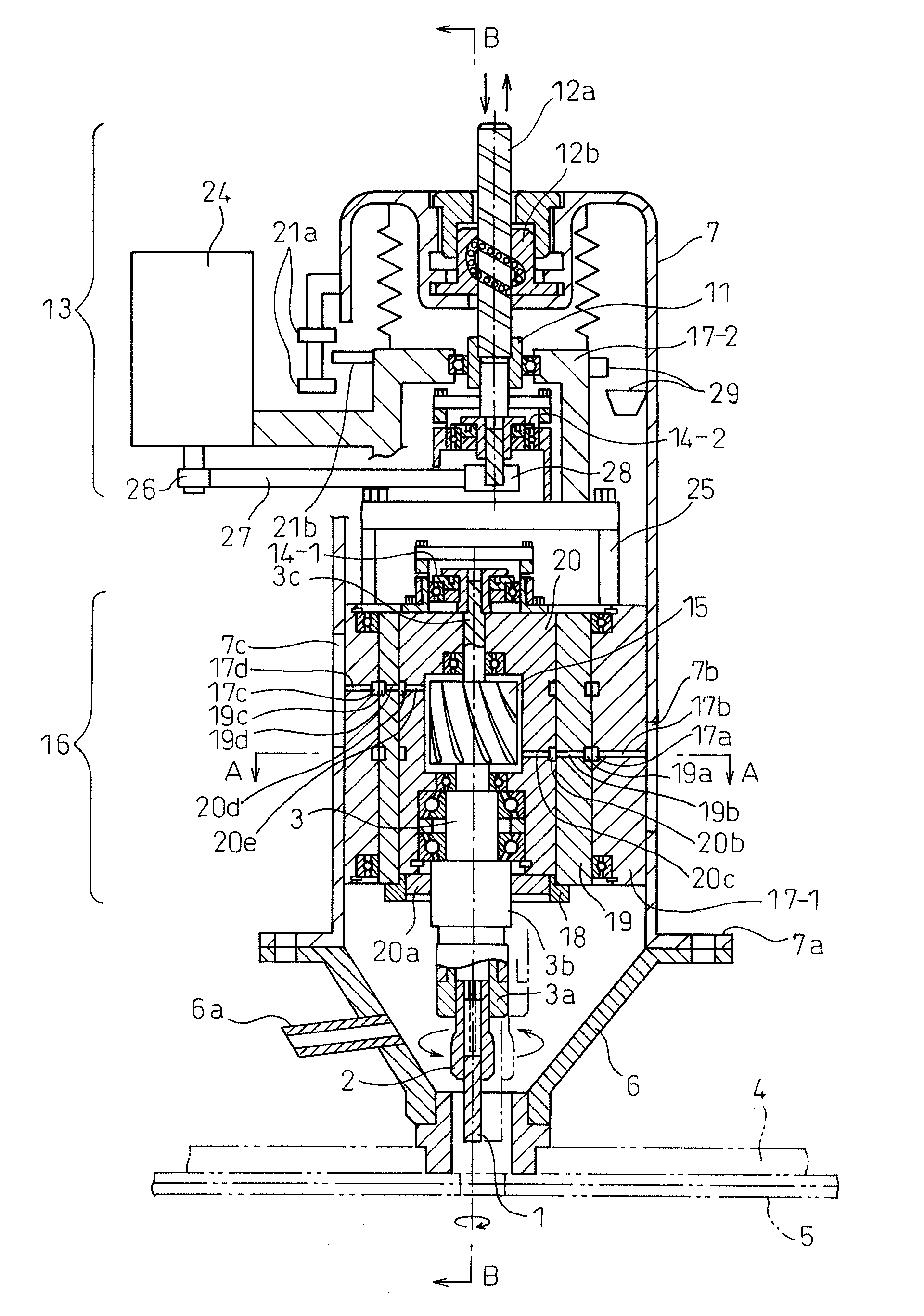
[0036]As shown in FIG. 1, an eccentric rotation drive mechanism 16 in a hole making apparatus of the present embodiment is provided with a cylindrical member (below, “inner cylinder”) 20 which houses an air driving means which is comprised of a first air motor 15 (for example, turbine etc.) which is provided at a rotation shaft portion 3 so that an end mill or other hole making tool 1 rotates about an axis of the rotation shaft portion 3 (C1 of FIG. 5) and simultaneously revolves around an center axis of an eccentric cylindrical member (C2 of FIG. 5), a first reduction device 14-1 (for example, Harmonic Drive®) which is coupled to the rotation shaft portion 3 which extends from a holder 2 which holds the hole making tool, and an eccentric cylindrical member (below, “outer cylinder”) 19 which is coupled to an output side of the reduction device, which houses a cylindrical member (inner cylinder) whic...

second embodiment

[0076]Below, the present invention will be explained.

[0077]If replacing the first air motor and second air motor which are shown in FIG. 1 with the first electric motor 31 and second electric motor 32 such as shown in FIG. 6 to obtain an electric motor-drive hole making apparatus and controlling the rotational speeds of the two electric motors by electronic control devices, it is possible to improve the hole making performance of the hole making apparatus much more compared with the case of air motor drive.

[0078]As shown in FIG. 6, the first electric motor 31 is connected to a power cord 34, while the second electric motor 32 is connected to a power cord 36. The power cord 34 passes through the first slide container 17-1 and supplies power to the power cord 34a which is provided passing through the outer cylinder 19 by the brush 33a which is provided at the inner surface of the slide container 17-1. Furthermore, power is supplied to the first electric motor 31 by the brush 33b which...


PUM

PropertyMeasurementUnit
diameteraaaaaaaaaa
diameteraaaaaaaaaa
diameteraaaaaaaaaa

Abstract

An eccentric rotation drive mechanism which is rotatably contained in a first slide container is provided with an outer cylinder, an internal cylinder which is housed at eccentric position thereof and a first air motor contained therein. One end of a rotation shaft portion, that is, a shaft of the first air motor is fastened to a hole making tool, the other end of which is coupled to the end surface of the outer cylinder through a first reduction device. The rotation of the air motor makes the hole making tool rotate and revolve and simultaneously the rotation of a second air motor mounted outside of a casing is transmitted to a ball screw through a rotation transmission device inside of a second slide container to advance and retreat a feed drive mechanism so as to machine a hole in a workpiece.

Description

TECHNICAL FIELD[0001]The present invention relates to a hole making apparatus which can use an end mill or the same kind tool as an end mill to machine a hole in fiber-reinforced plastics, their laminates, and other workpieces at a high accuracy.BACKGROUND ART[0002]Recently, to lighten the weight of fuselages of aircrafts and bodies of automobiles and other vehicles, etc., the fuselages themselves, the bodies themselves, or their components have been formed by fiber-reinforced plastics (FRP). Such fiber-reinforced plastics are being provided in various forms such as thermosetting plastics which contain carbon fibers as reinforcing fibers inside them (CFRP), thermosetting plastics which contain glass fibers as reinforcing inside them (GFRP), and thermosetting plastics which contain aromatic polyamide, aromatic polysulfone, aromatic polyimide, and other heat resistant synthetic resin fibers as reinforcing fibers inside them. Usually, it is known to stack a plurality of fiber-reinforce...

Claims


Application Information

Patent Timeline
Patent Type & Authority Applications(United States)
IPC IPC(8): B23C1/06
CPCB23B51/0036B23B2226/275Y10T409/307616B23C2220/52B23C3/02
Inventor YAGISTA, HUKUZO
Owner YAGASITA HUKUZO
Why Eureka
Try Eureka