Tunneling magnetoresistance (TMR) read sensor with low-contact-resistance interfaces

Inactive Publication Date: 2012-11-29
HITACHI GLOBAL STORAGE TECH NETHERLANDS BV
View PDF4 Cites 5 Cited by
  • Summary
  • Abstract
  • Description
  • Claims
  • Application Information

AI Technical Summary

Benefits of technology

[0008]The invention provides a TMR read sensor with low-contact-resistance metal/metal, metal/oxide and oxide/metal interfaces. The low-contact-resistance metal/metal interfaces in a reference or sense layer structure are in-situ formed in a high-vacuum deposition module of a sputtering system, without exposures to low vacuum in a transfer module and damages caused by a plasma treatment conducted in an etching module. The low-contact-resistance metal/oxide interface is formed by utilizing a thin Co—Fe—B reference layer and a t

Problems solved by technology

In this miniaturization progress of the TMR read sensor, its resistance will progressively inc

Method used


Image

  • Tunneling magnetoresistance (TMR) read sensor with low-contact-resistance interfaces
  • Tunneling magnetoresistance (TMR) read sensor with low-contact-resistance interfaces
  • Tunneling magnetoresistance (TMR) read sensor with low-contact-resistance interfaces

Examples


Embodiment Construction

[0026]The following description is of the best embodiments presently contemplated for carrying out the invention. This description is made for the purpose of illustrating general principles of the invention and is not meant to limit inventive concepts claimed herein.

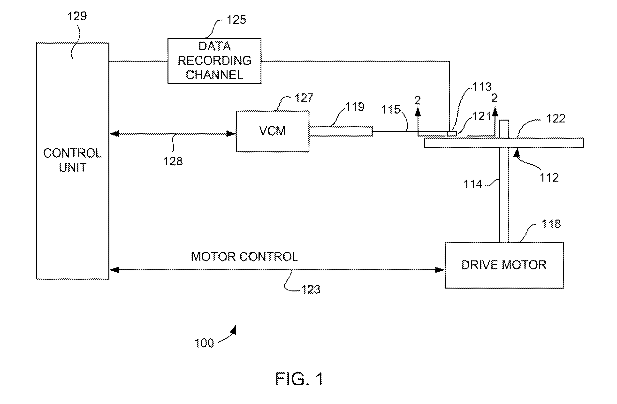
[0027]Referring now to FIG. 1, there is shown a magnetic disk drive 100 embodying the invention. As shown in FIG. 1, at least one rotatable magnetic disk 112 is supported on a spindle 114 and rotated by a disk drive motor 118. Magnetic recording on each magnetic disk is performed at annular patterns of concentric data tracks (not shown) on the magnetic disk 112.

[0028]At least one slider 113 is positioned near the magnetic disk 112, each slider 113 supporting one assembly of write and read heads 121. As the magnetic disk 112 rotates, the slider 113 moves radially in and out over the disk surface 122 so that the assembly of write and read heads 121 may access different data tracks on the magnetic disk 112. Each slider 113 ...


PUM


Abstract

The invention provides a TMR read sensor with low-contact-resistance metal/metal, metal/oxide and oxide/metal interfaces. The low-contact-resistance metal/metal interfaces in a reference or sense layer structure are in-situ formed in a high-vacuum deposition module of a sputtering system, without exposures to low vacuum in a transfer module and damages caused by a plasma treatment conducted in an etching module. The low-contact-resistance metal/oxide interface is formed by utilizing a thin Co—Fe—B reference layer and a thick Co—Fe reference layer to reduce boron diffusion and segregation caused by annealing. The low-contact-resistance oxide/metal interface is formed by replacing a Co—Fe—B sense layer with a Co-rich Co—Fe sense layer to eliminate boron diffusion and segregation caused by annealing. With the low-contact-resistance metal/metal, metal/oxide and oxide/metal interfaces, the TMR read sensor exhibits a junction resistance-area product of below 0.6 Ω-μm2, while maintaining a low ferromagnetic coupling field and a high TMR coefficient.

Description

FIELD OF THE INVENTION[0001]The invention relates to non-volatile magnetic storage devices and more particularly to a magnetic disk drive including a tunneling magnetoresistance (TMR) read sensor with low-contact-resistance interfaces.BACKGROUND OF THE INVENTION[0002]One of many extensively used non-volatile magnetic storage devices is a magnetic disk drive that includes a rotatable magnetic disk and an assembly of write and read heads. The assembly of write and read heads is supported by a slider that is mounted on a suspension arm. The suspension arm is supported by an actuator that can swing the suspension arm to place the slider with its air bearing surface (ABS) over the surface of the magnetic disk.[0003]When the magnetic disk rotates, an air flow generated by the rotation of the magnetic disk causes the slider to fly on a cushion of air at a very low elevation (fly height) over the magnetic disk. When the slider rides on the air, the actuator moves the suspension arm to posit...

Claims


Application Information

Patent Timeline
IPC IPC(8): H01L29/82H01L21/02
CPCG11B5/3909G11B5/3932G01R33/098H01L43/08B82Y40/00H01L43/12H01F10/3254H01F10/3295H01F41/303H01L43/10H10N50/01H10N50/85H10N50/10
Inventor LIN, TSANN
Owner HITACHI GLOBAL STORAGE TECH NETHERLANDS BV
Why Eureka
Try Eureka