Rechargeable batteries

Active Publication Date: 2012-12-06
BAE SYSTEMS PLC
View PDF3 Cites 15 Cited by
  • Summary
  • Abstract
  • Description
  • Claims
  • Application Information

AI Technical Summary

Benefits of technology

[0003]There is increasing demand for higher battery gravimetric or volumetric efficiency in terms of specific energy

Problems solved by technology

A potential difficulty with existing structures is that the adhesion between the active material and the matrix material required to retain the

Method used


Image

  • Rechargeable batteries
  • Rechargeable batteries
  • Rechargeable batteries

Examples


example 1

[0028]In this Example suitable matrix materials were prepared for impregnating a glass fibre sheet material in order to provide a separator structure for a battery, using different porogen:epoxy ratios to provide different levels of porosity. 4.1 g of Struers EpoFix was mixed with 0.5 g EpoFix hardener and a measured mass of PEG200 was added as a porogen. The materials were spread onto a non-stick film and cured for 12 hours at 60° C. Once cured, sample sections of the films were cut to size and soaked in water overnight to dissolve the porogen. The films were then oven dried at 60° C. for 2 hours. The change in mass was used to determine the average porosity with different mass ratios of PEG to epoxy. The results are given in the table below.

Mass ratio PEG200:EPOXYAverage Porosity %1:1222:1383:160

[0029]Thus a separator structure may be made by mixing Struers EpoFix resin suitably loaded with PEG200 and impregnating 200 gsm E-glass fabric with the mixture, allowing the material to c...

example 2

[0032]In this Example, the effect of the order of mixing the materials was assessed.

[0033]Electrode pastes were made up from the following ingredients: 4.1 g Struers Epofix resin, 0.5 g of EpoFix hardener, 0.35 g of carbon powder, 3 g of electrochemically active material (Ni(OH)2 or ZnO) of mean particle size between 5 μm and 10 μm, and 12.3 g of PEG200.

[0034]For the first set of electrodes the dry ingredients were mixed with the epoxy resin and then the PEG was added, whilst for the second set the dry ingredients were mixed with the PEG first and then the epoxy was added. Equal masses of epoxy pastes were used to from composite electrodes on plain weave 200 gsm carbon fibre fabrics. The electrodes were cured and soaked to remove the residual PEG. They were then assembled into cells and filled with electrolyte (40% KOH solution saturated with approximately 50 g / l of ZnO added). Capacity tests were made and the energy density for the epoxy-first sample was measured as 0.28 Wh / kg wher...

example 3

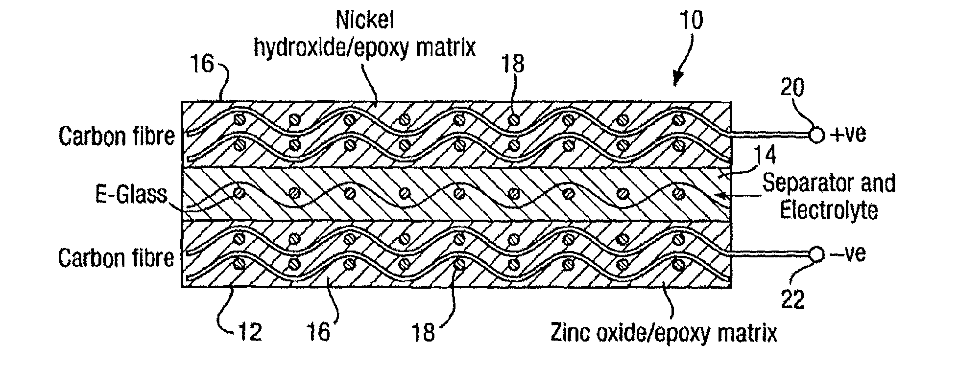
[0038]In order to make up a rechargeable battery first and second porous electrode layers are prepared by making up a respective first and second matrix material epoxy mixtures by one or more of the methods described above and applying them to impregnate layers of conducting carbon fibre reinforcing layers. A porous separator layer is then made by one or more of the methods described above. The various layers may then be partially cured before assembling the electrode:separator:electrode structure to reduce moving or mixing of the ingredients, or they may be assembled in their uncured states. After curing the porogen is flushed out with, for example, warm water and the structure allowed to dry. Electrolyte is then introduced into the cell by vacuum and / or high pressure and / or by simple immersion to induce a capillary action. On particular samples, fill or drain points may be formed in the cell to provide leakproof access through one of the electrode layers. The electrolyte again may...


PUM

PropertyMeasurementUnit
Lengthaaaaaaaaaa
Fractionaaaaaaaaaa
Thicknessaaaaaaaaaa

Abstract

A rechargeable battery is disclosed having electrode and separator structures which are made up of fibre-reinforced composite material, thereby allowing the battery itself to serve as an integral structural component. The utilisation or efficiency of the rechargeable battery is considerably enhanced by rendering at least part of the matrix material of the electrodes and the separator porous, thereby to facilitate improved access to active sites on the electrodes, with the porosity in the separator allowing improved ion transport, both of which enhance cell operation. The porous structure also provides improved electrolyte containment and retention in the event of damage.

Description

BACKGROUND TO THE INVENTION[0001]This invention relates to rechargeable batteries and in particular, but not exclusively, to rechargeable batteries which are incorporated into a structural component such as, for example, a load-bearing element or wing surface.BACKGROUND ART[0002]We have previously proposed an architecture for such devices in which the electrodes are formed from respective fibre-reinforced layers of matrix material (such as epoxy). Various cell chemistries are possible and will be well known to those skilled in the art. The matrix material of the electrodes contains an electro-chemically active material together with a conductive additive such as carbon powder which acts as a current collector, passing current from the electro-chemically active material to the fibres of the fibre-reinforcing layer, which are electrically conducting. As an example therefore, in a nickel zinc cell, the electro-chemically active material of the anode may be nickel hydroxide particles an...

Claims


Application Information

Patent Timeline
IPC IPC(8): B05D5/12H01M4/64H01M2/14
CPCB64C3/26Y10T29/49108H01M2/164H01M2/1673H01M4/0416H01M4/139H01M4/26H01M4/62H01M4/621H01M4/622H01M4/624H01M4/625H01M4/74H01M10/04H01M10/0585H01M10/12H01M10/281H01M10/287H01M10/30H01M10/32H01M10/345H01M10/465H01M2004/021Y02E60/122Y02E60/124Y02E60/126Y02T10/7016H01M10/058H01M2/1606Y02E60/10Y02P70/50H01M50/44H01M50/46Y02T10/70
Inventor HUCKER, MARTYN JOHNDUNLEAVY, MICHAELDYKE, AMY ELIZABETHHAQ, SAJAD
Owner BAE SYSTEMS PLC
Why Eureka
Try Eureka