

Hydrothermal hydrocatalytic treatment of biomass
- Summary
- Abstract
- Description
- Claims
- Application Information
AI Technical Summary
Benefits of technology
Problems solved by technology
Method used
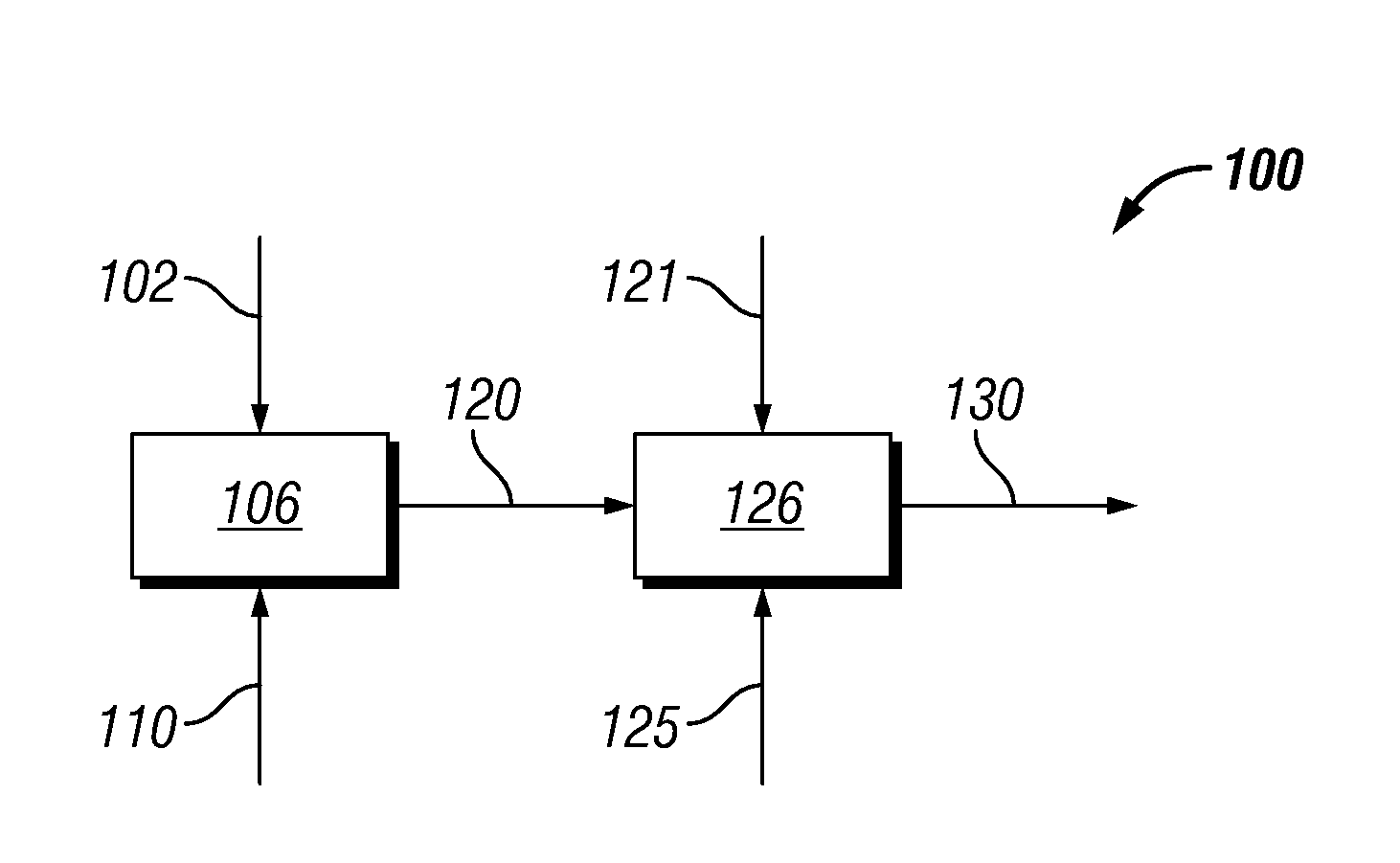
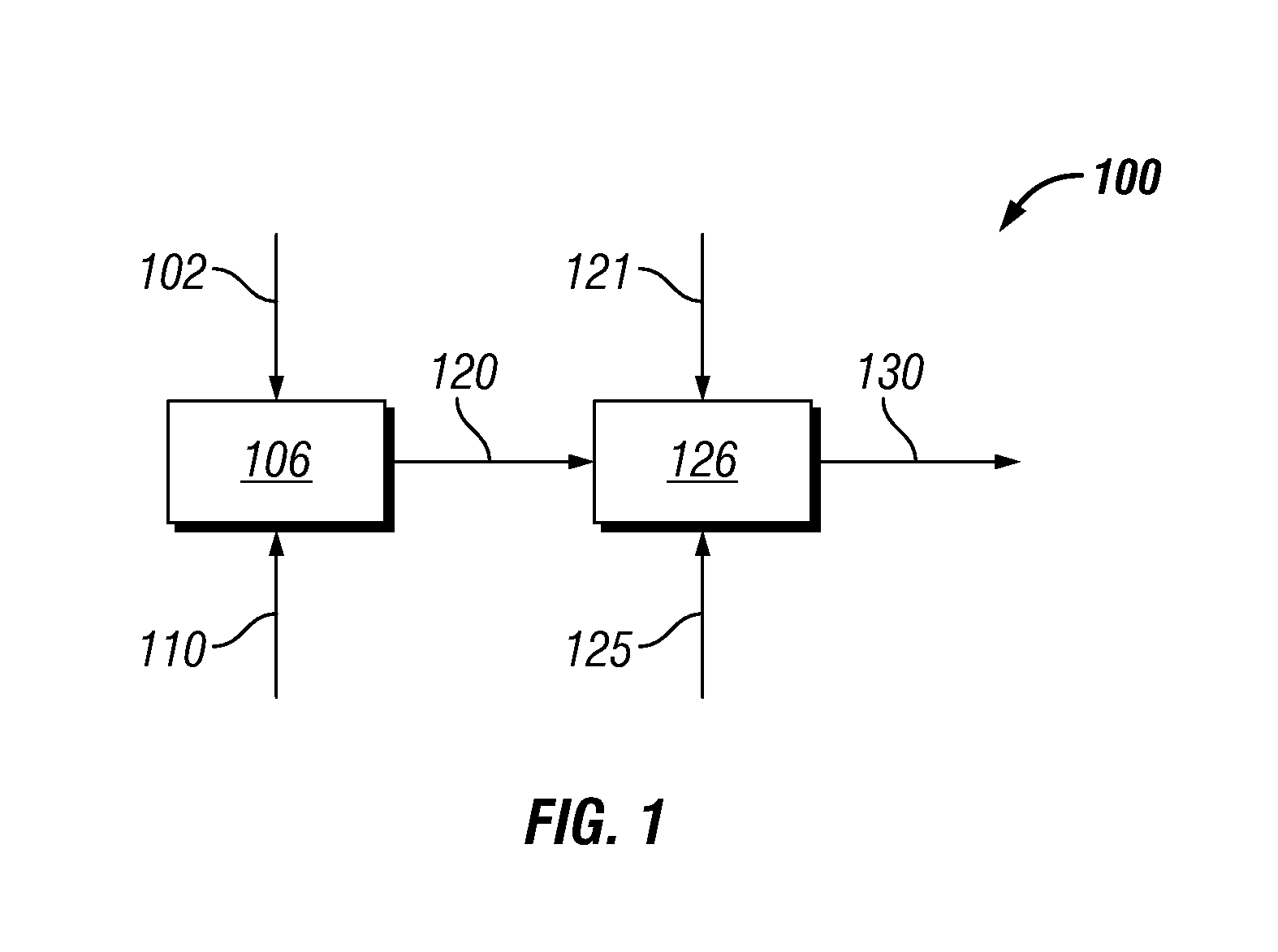
Image

Examples
example 1
pH Buffering Only at Start of Reaction
[0087]A 100-ml Parr reactor was charged with 60.0 grams of 50% 2-propanol in deionized water solvent, 0.9 grams of sulfided DC2534 catalyst (from Criterion Catalyst and Technologies L.P.) containing 1-10% cobalt oxide and molybdenum trioxide (up to 30 wt %) on alumina, and less than 2% nickel, nominal particle size 2-100 microns), 0.1972 grams of potassium carbonate buffer, and 7.0 grams of ground soft pine wood (39% moisture; 67.8% carbohydrate on dry basis). The reactor was pressured to 65 bar with H2, and heated to 240° C. for 5 hours, with stirring at 550 rpm. A 7 gram sample of liquid was removed via 0.5-micron filtered dip tube, and 7 grams of softwood was added to effect a second cycle. This process was repeated for 5 cycles. The pH measured for removed samples were 4.93, 4.45, 4.11, 3.78, and 3.55 for cycles 1 through 5 respectively.
[0088]At the end of cycle 5, 6.0 grams of glycerol were added to the reactor, and the reactor contents wer...
example 2
pH Buffering Throughout Reaction Cycles to Maintain pH>4.6
[0089]Example 1 was repeated with addition of between 0.04 and 0.06 grams of potassium carbonate at the start of each cycle, such that pH remained greater than 5.2 when measured at the end of each cycle, except for an excursion to 4.6 for the first cycle. Cobalt in filtrate after 6 cycles was only 11 ppm, or less than half the leached cobalt relative to that observed in the sequence of Example 1, where continuous buffering was not applied.
example 3
pH Buffering Throughout Reaction Cycles to Maintain pH>5.5
[0090]The sequence of experiments of Example 1 was repeated, with addition of between 0.08 and 0.10 grams of potassium carbonate each cycle. pH was maintained between 5.5 and 5.8. Measured glycerol conversion after 6 cycles was 34% of that observed with fresh catalyst, or nearly 10-fold better than that observed for Example 1, where continuous buffering was not applied.
[0091]These examples show that continuous buffer addition is needed to offset acidity generated in the course of hydrothermal, hydrocatalytic treatment of biomass, to maintain pH greater than 3.5. Use of continuous or semi-continuous buffering to maintain pH greater than 4.5 gaves reduced leaching of cobalt metal from the catalyst, which can prolong catalyst life. A 10-fold improvement in activity was observed after 6 cycles with pH buffering to maintain pH greater than 5.5, relative to the activity observed in the absence of buffer addition each cycle, where a...
PUM
| Property | Measurement | Unit |
|---|---|---|
| Temperature | aaaaa | aaaaa |
| Temperature | aaaaa | aaaaa |
| Solubility (mass) | aaaaa | aaaaa |
Abstract
Description
Claims
Application Information