
Welded steel pipe for linepipe having high compressive strength and excellent sour gas resistance and manufacturing method thereof

a technology of welded steel pipe and sour gas resistance, which is applied in the field of linepipes, can solve the problems of deterioration of productivity, reduced compressive yield strength, and low roundness of the linepipe used for offshore pipelines, and achieves excellent toughness, high compressive strength, and high compressive strength.

Active Publication Date: 2013-01-03
JFE STEEL CORP
View PDF1 Cites 13 Cited by
  • Summary
  • Abstract
  • Description
  • Claims
  • Application Information

AI Technical Summary

Benefits of technology

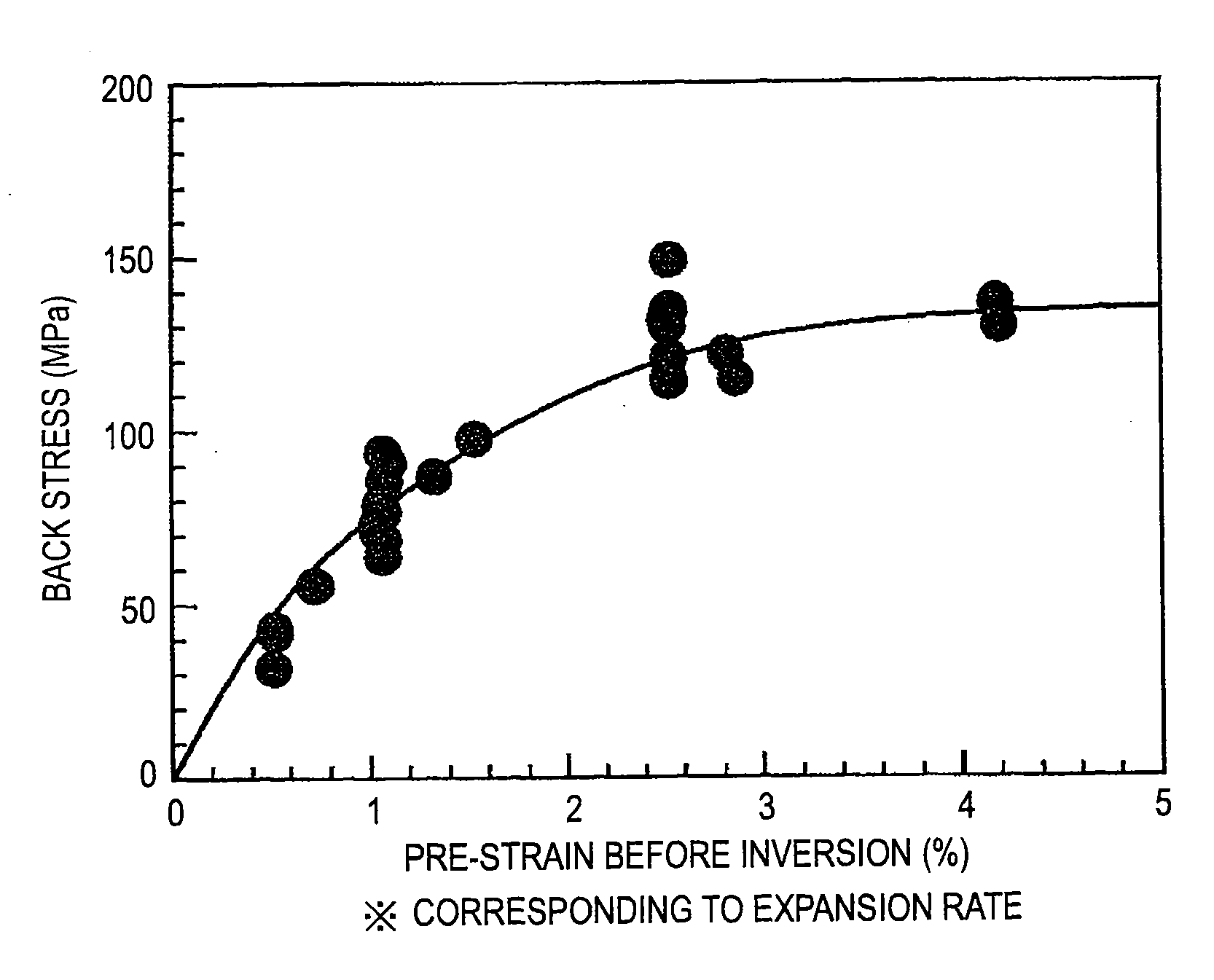
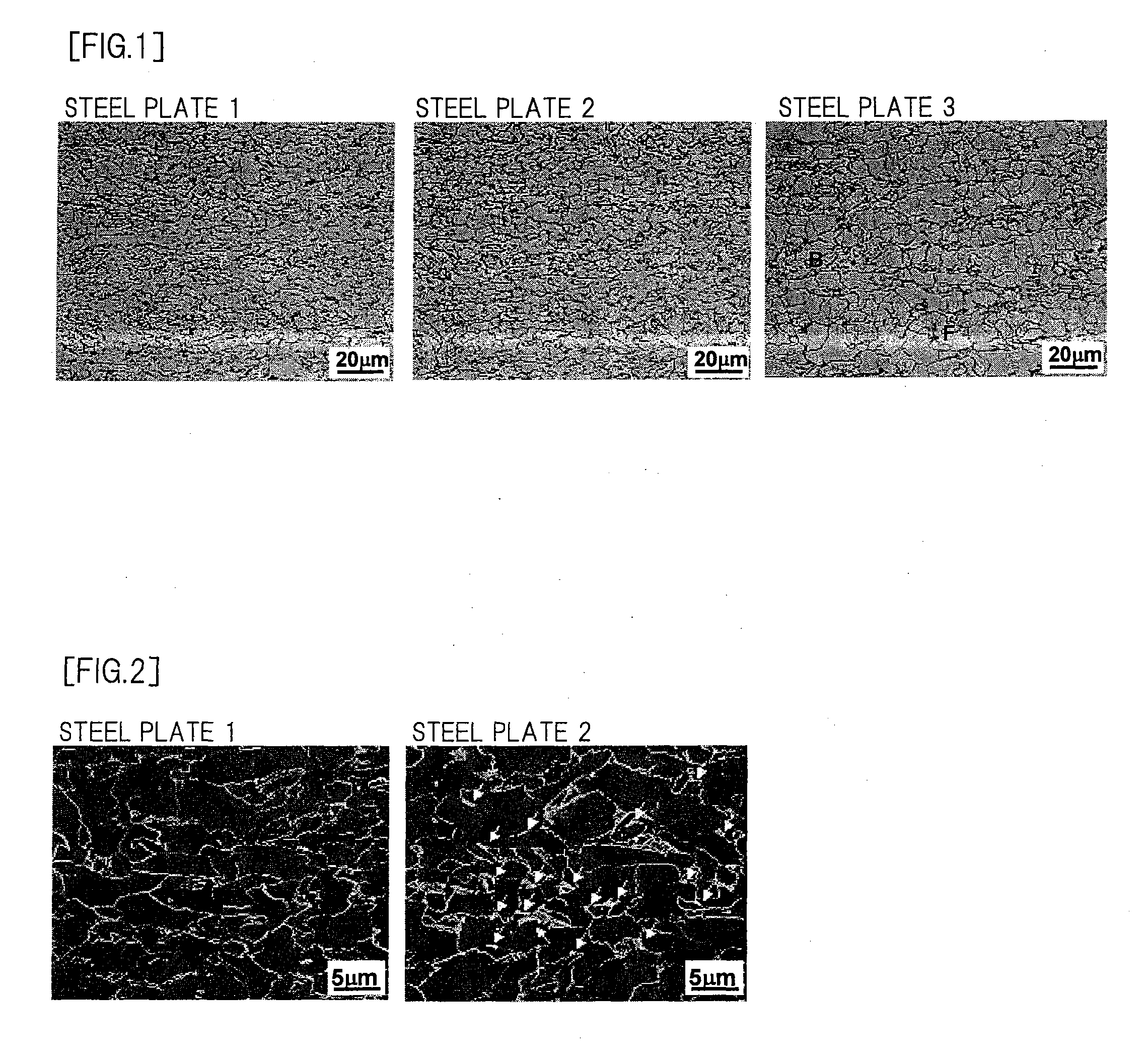
The present invention aims to provide a welded steel pipe for a sea-bed pipeline that has high strength, excellent toughness, high compressive strength, and excellent sour gas resistance. To achieve this, the invention focuses on optimizing the metal microstructure of the steel material, specifically by decreasing the ferrite-bainite interface and the hard second phase, such as MA, where dislocation is integrated. Additionally, by properly setting the content of carbide formation elements such as Nb, interaction between dislocation and solid solute C is enhanced, impeding the movement of dislocation at the time of inversion of a load and suppressing lowering of compressive strength due to back stress. Overall, the invention provides a solution for acquiring a strong and durable steel pipe for use in sea-bed pipeline applications.

Problems solved by technology

Further, the linepipe used for offshore pipeline is required to exhibit high roundness.
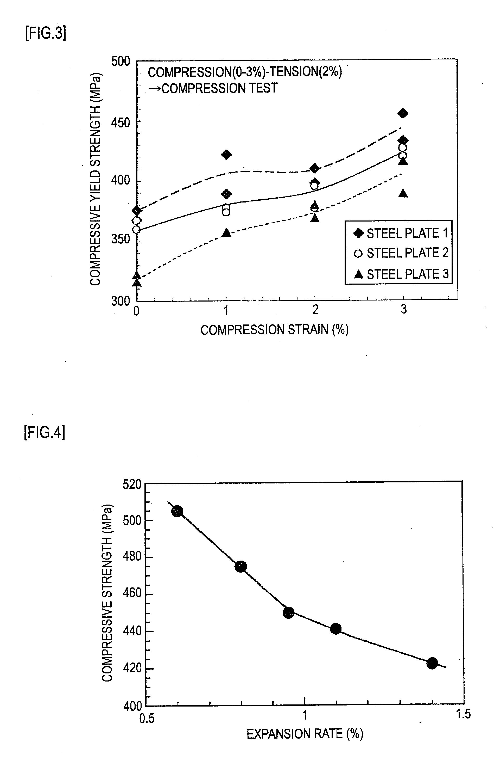
However, in the case of a steel pipe which is manufactured through a pipe expanding process in cold forming, there exists a drawback that compressive yield strength is lowered by a Bauschinger effect.
However, it is necessary to continue Joule heating for holding the temperature for 5 minutes or more after the pipe expansion and hence, productivity is deteriorated.
However, with respect to the method disclosed in patent document 2, it is extremely difficult to separately control the heating temperature and the heating time of the outer surface and the inner surface of the steel pipe in terms of the actual manufacture of a steel pipe, and particularly to control quality of the steel pipe in a mass production process is extremely difficult.
The method disclosed in patent document 3 also has a drawback that it is necessary to set a stop temperature of accelerated cooling in the manufacture of the steel plate at the low temperature of 300° C. or below and hence, the distortion of the steel plate is increased whereby when a steel pipe is made from the steel plate by a UOE forming process, roundness of the steel pipe is lowered.
The method disclosed in patent document 3 further has a drawback that since the accelerated cooling is performed from the Ar3 temperature or above, it is necessary to perform rolling at a relatively high temperature so that fracture toughness is deteriorated.
However, when the expansion rate is low, it becomes difficult for the steel pipe to maintain roundness thus giving rise to a possibility that collapse resistant performance of the steel pipe is deteriorated.
However, a portion of the steel pipe which may cause a problem on collapse in the actual pipeline construction is a portion of the steel pipe which reaches a sea bed and is subjected to bending deformation (sag-bend portion), and the pipeline is constructed on the sea bed by girth weld irrelevant to the position of the seam weld of the steel pipe.
Accordingly, even when the end point to the seam weld is set on a major axis, the method does not exhibit any practical effects.
However, in the technique described in patent document 6, it is necessary to perform heating such that heating reaches a center portion of the steel plate at the time of reheating thus causing lowering of DWTT property.
Accordingly, the application of the technique to a linepipe having a heavy wall thickness for deep sea has been difficult.

Method used


Image

  • Welded steel pipe for linepipe having high compressive strength and excellent sour gas resistance and manufacturing method thereof
  • Welded steel pipe for linepipe having high compressive strength and excellent sour gas resistance and manufacturing method thereof
  • Welded steel pipe for linepipe having high compressive strength and excellent sour gas resistance and manufacturing method thereof

Examples


embodiment

[0090]Slabs are manufactured from steels (kinds of steels A to K) having chemical compositions shown in Table 1 by a continuous casting process, and heavy-wall-thickness steel plates (No. 1 to 23) having plate thicknesses of 30 mm and 38 mm were manufactured using the slabs. Manufacturing conditions of the steel plates and manufacturing conditions of the steel pipes, metal microstructures, mechanical properties and the like of the steel pipes are respectively shown in Table 2 and Table 3. In reheating treatment at the time of manufacturing the steel plate, reheating was performed using an induction heating furnace which is mounted on the same line as an accelerated cooling facility. A surface layer temperature at the time of reheating is a surface temperature of the steel plate at an exit of the induction heating furnace, and a steel plate temperature at a point of time that a surface layer temperature and a center temperature become substantially equal to each other after heating i...


PUM

PropertyMeasurementUnit
grain sizeaaaaaaaaaa
temperatureaaaaaaaaaa

Abstract

Provided is a steel pipe for a linepipe having high compressive strength, a heavy wall thickness and sour gas resistance. The steel pipe has the composition which contains by mass % 0.02 to 0.06% C, 0.01 to 0.5% Si, 0.8 to 1.6% Mn, 0.012% or less P, 0.0015% or less S, 0.01 to 0.08% Al, 0.005 to 0.050% Nb, 0.005 to 0.025% Ti, 0.0005 to 0.0035% Ca, 0.0020 to 0.0060% N, and Fe and unavoidable impurities as a balance. The steel pipe has metal microstructure where a fraction of bainite is 80% or more, a fraction of M-A constituent is 2% or less and an average grain size of bainite is 5 μm or less.

Description

CROSS-REFERENCE TO RELATED APPLICATIONS[0001]This application is the U.S. National Phase application of PCT International Application No. PCT / JP2010 / 071536, filed Nov. 25, 2010, and claims priority to Japanese Patent Application No. 2009-267256, filed Nov. 25, 2009, the disclosures of which PCT and priority applications are incorporated herein by reference in their entireties for all purposes.FIELD OF THE INVENTION[0002]The present invention relates to a linepipe having excellent sour gas resistance for transporting crude oil, natural gas or the like, and more particularly to a welded steel pipe for a linepipe having high compressive strength and excellent sour gas resistance suitably used as a linepipe for deep-sea having a heavy wall thickness to exhibit high collapse resistant performance, and a manufacturing method thereof. The compressive strength used in the present invention means, unless otherwise specified, compressive yield strength or 0.5% compressive proof strength. Also...

Claims


Application Information

Patent Timeline
Patent Type & Authority Applications(United States)
IPC IPC(8): F16L9/02C21D9/08
CPCB21C37/08F17D1/16C21D1/20C21D8/0226C21D8/0263C21D8/10C21D9/50C21D2211/002C21D2211/008C22C38/001C22C38/002C22C38/02C22C38/04C22C38/06C22C38/12C22C38/14C22C38/44C22C38/46C22C38/48C22C38/50B21C37/30
Inventor ISHIKAWA, NOBUYUKITANIZAWA, AKIHIKOSUEYOSHI, HITOSHIHORIE, MASAYUKIKIYOTO, YASUMITSUSHIKANAI, NOBUO
Owner JFE STEEL CORP
Learn More