Reduced Q Low Frequency Antenna

Active Publication Date: 2013-01-03
ROKE MANOR RES LTD
View PDF6 Cites 16 Cited by
  • Summary
  • Abstract
  • Description
  • Claims
  • Application Information

AI Technical Summary

Benefits of technology

[0008]Embodiments of the invention provide an improved rod antenna and antenna tank circuit which make use of negative feedback to reduce the Q of the antenna, but which also makes use of a different coil tapping arrangement to significantly reduce electric field susceptibility on the detected signal from the main coil and/or different biasing arrangements to reduce noise. More particularly, in some embodiments of the invention the main detector coil of the antenna has a centre tap that is AC grounded with signal taps then being taken from the opposite ends of the main coil, and being respectively fed to the inputs of a differential amplifier. The output of the differential amplifier is then fed to the magnetic circuit of the rod antenna via a second inductor winding that is magnetically

Problems solved by technology

However, the inductor-capacitor combination provides a frequency response with very high Q, which, whilst acceptable for the reception of narrow band signals, is not acceptable for the reception of wide band signals, where the bandwidth is a significant portion of the antenna centre frequency.
A rod

Method used


Image

  • Reduced Q Low Frequency Antenna
  • Reduced Q Low Frequency Antenna
  • Reduced Q Low Frequency Antenna

Examples


Embodiment Construction

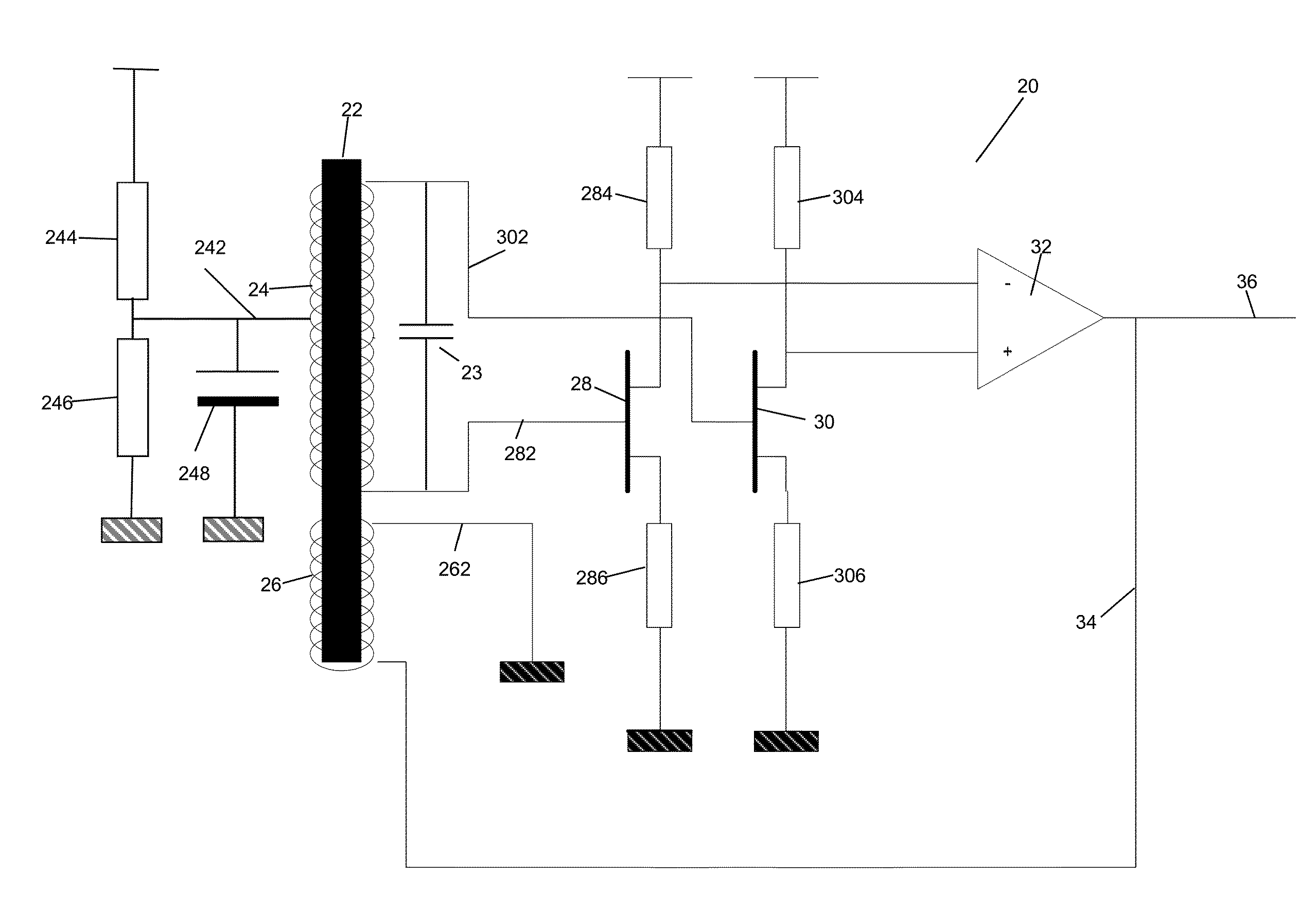
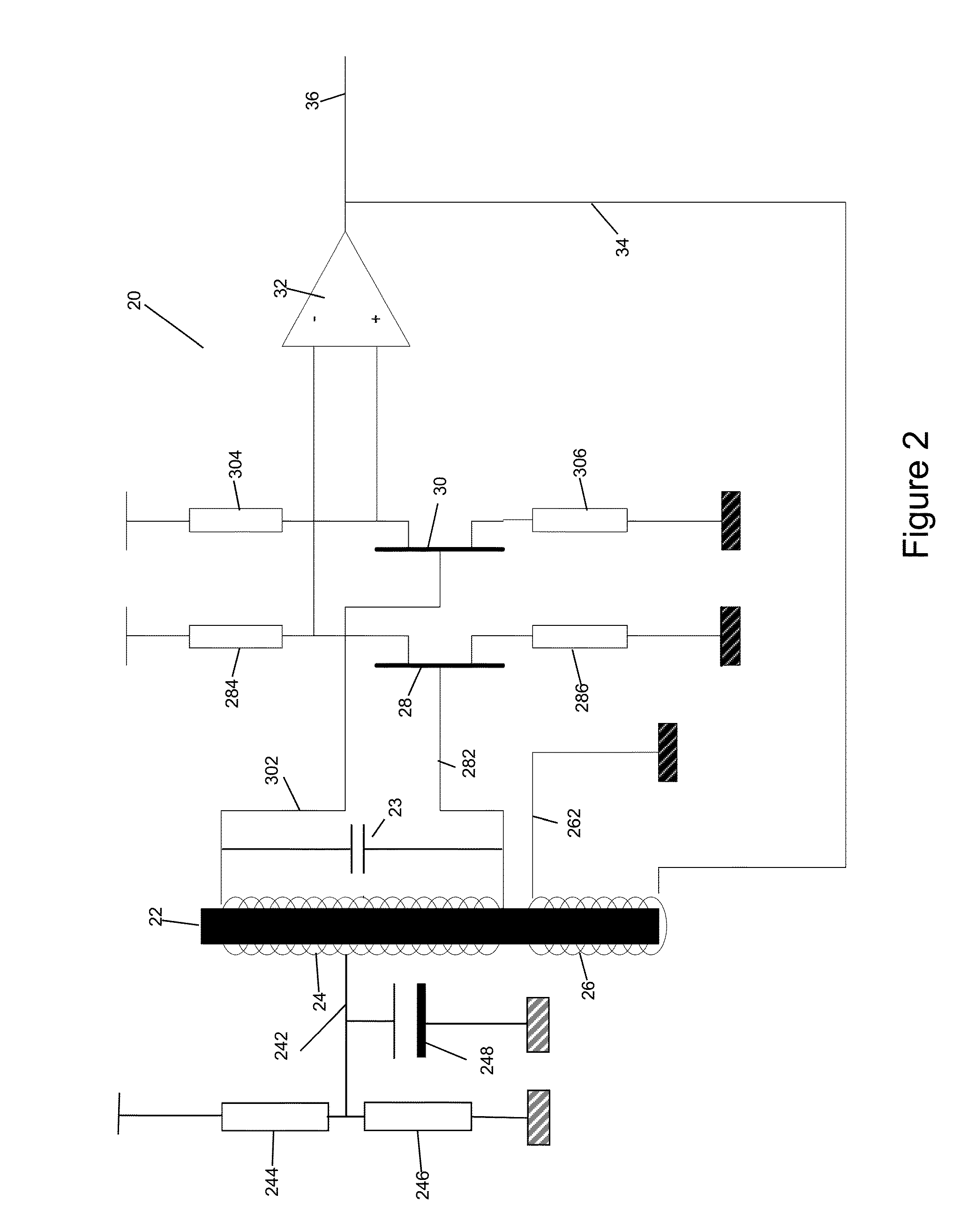
[0037]A first embodiment of the present invention is shown in FIG. 2. Here, a rod antenna circuit 20 is provided, comprising a former 22, such as a ferrite rod or the like, around which a first, main, antenna coil 24 is wound. In this embodiment the coil 24 has a centre tap 242 which is connected to an AC ground via AC grounding capacitor 248. The centre tap is DC biased via a divider formed from resistors 244 and 246. Outputs of the coil 24 are taken from opposite ends of the coil, with a first output line 302 feeding into the base (or gate) of a first transistor 30. A second output line 282 at the opposite end of the coil feeds a signal to the base (or gate) of a second transistor 28, via line 282. The first transistor 30 is provided with biasing resistors 304 and 306 respectively connected to the collector (drain) and emitter (source) of the transistor. Similarly, the second transistor 28 is also provided with biasing resistors 284 and 286, respectively connected to the collector...


PUM


Abstract

A rod antenna and antenna circuit are described which make use of negative feedback to reduce the Q of the antenna, but which also makes use of a different coil tapping arrangement to significantly reduce electric field susceptibility on the detected signal from the main coil as well as different biasing arrangements to reduce noise. More particularly, in some embodiments of the invention the main detector coil of the antenna has a centre tap that is AC grounded with signal taps then being taken from the opposite ends of the main coil, and being respectively fed to the inputs of a differential amplifier. The output of the differential amplifier is then fed to the magnetic circuit of the rod antenna via a second inductor winding that is magnetically coupled to the resonance circuit of the main antenna coil.

Description

CROSS-REFERENCE TO RELATED APPLICATIONS[0001]This application claims priority benefit to United Kingdom Patent Application No. 1111120.0, filed Jun. 29, 2011, which is hereby incorporated by reference.TECHNICAL FIELD[0002]The present invention relates to a rod antenna, and in particular a rod antenna which has reduced Q by making use of negative feedback.BACKGROUND TO THE INVENTION AND PRIOR ART[0003]Rod antennas are known in the art for the receipt of low frequency signals in the range typically of a few tens of kHz up to 1 to 2 MHz. A conventional low frequency rod antenna usually comprises a number of turns of wire on a former, the former usually being a ferrite rod. The coil forms an inductor and the antenna may be tuned to a particular frequency by adding a capacitor for example in parallel with the inductor so that the inductor and capacitor form a resonant circuit. However, the inductor-capacitor combination provides a frequency response with very high Q, which, whilst accept...

Claims


Application Information

Patent Timeline
IPC IPC(8): H01Q7/00H01Q21/00
CPCH01Q7/08H01Q23/00H01Q21/30G01S1/245H04B1/18
Inventor LEIGHTON, GRAHAM RICHARD
Owner ROKE MANOR RES LTD
Why Eureka
Try Eureka