Oval Aortic Valve

a technology of aortic valve and valve body, which is applied in the field of transcatheter aortic valve implantation, can solve the problems of aortic valve regurgitation, reflux in the typical trileaflet valve, and the performance of the tavi device is reduced, and achieves the effect of soft flexure and large outward for

Inactive Publication Date: 2013-01-24
DRASLER WILLIAM JOSEPH
View PDF2 Cites 13 Cited by
  • Summary
  • Abstract
  • Description
  • Claims
  • Application Information

AI Technical Summary

Benefits of technology

[0013]In still another embodiment of the present invention, the frame is made with a wall structure that includes hinges and struts with a special dimensioning. The hinge width is narrower than the strut width such that the hinge flexes during expansion of the frame and the strut does not. The strut depth is smaller than the hinge depth such that the strut flexes elastically during a shape change to an oval shape in its fully expanded configuration. The hinge does not flex during such an oval deformation. The hinge length is very short in comparison to the strut length such that during a balloon expansion the hinge formed from the balloon expandable frame material will deform plastically while the strut will remain elastic during a crush deformation due to the thin depth of the strut. The hinge length extends from one transition region to another and undergoes substantially all of the deformation that occurs during the expansion deformation of the stent during deployment. For a self-expanding stent the stent can retain a large outward force as controlled by the hinge depth and width while the strut allows for very soft flexure due to its thin depth in order to form an oval shape.

Problems solved by technology

Thus when a round stented valve is placed into this oval configuration, two issues arise that reduce the performance of the TAVI device.
First, the stent of the TAVI device can begin to take on a slight oval shape and thereby cause reflux in the typical trileaflet valve due to a lack of tight coaptation of the leaflets with each other.
Reflux of blood through inadequately coapted leaflets or perivalvular leaks around the stent due to the oval shaped annulus can lead to aortic valve regurgitation, left ventricular heart failure, and possibly death.
The standard trileaflet valve design is negatively impacted when it is unduly forced into an oval shape resulting in intravalvular leakage of blood.
Such intravalvular leaks can also occur when a valve of too large of a perimeter is placed into a native annular perimeter that is of a lower diameter or perimeter.

Method used


Image

  • Oval Aortic Valve
  • Oval Aortic Valve
  • Oval Aortic Valve

Examples


Embodiment Construction

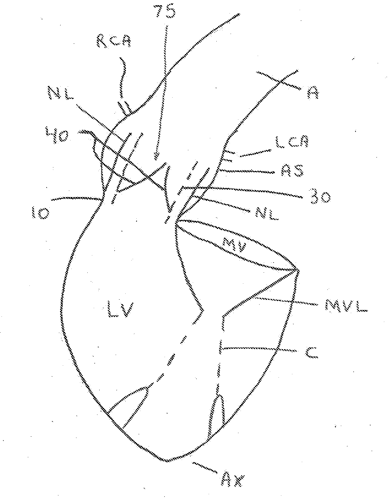
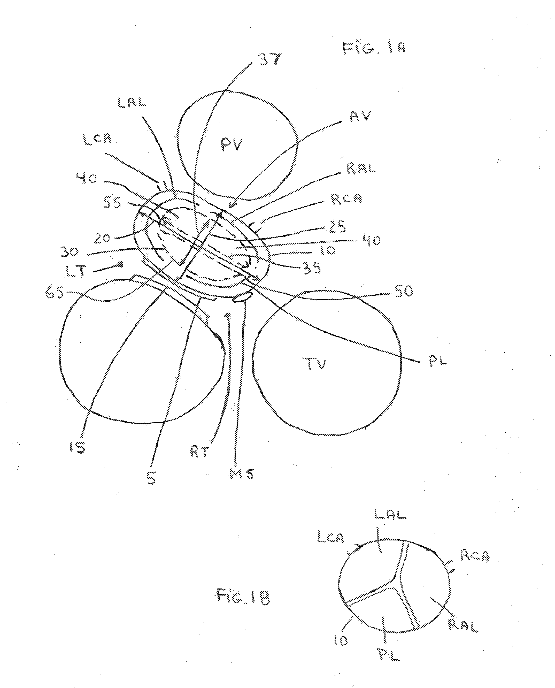
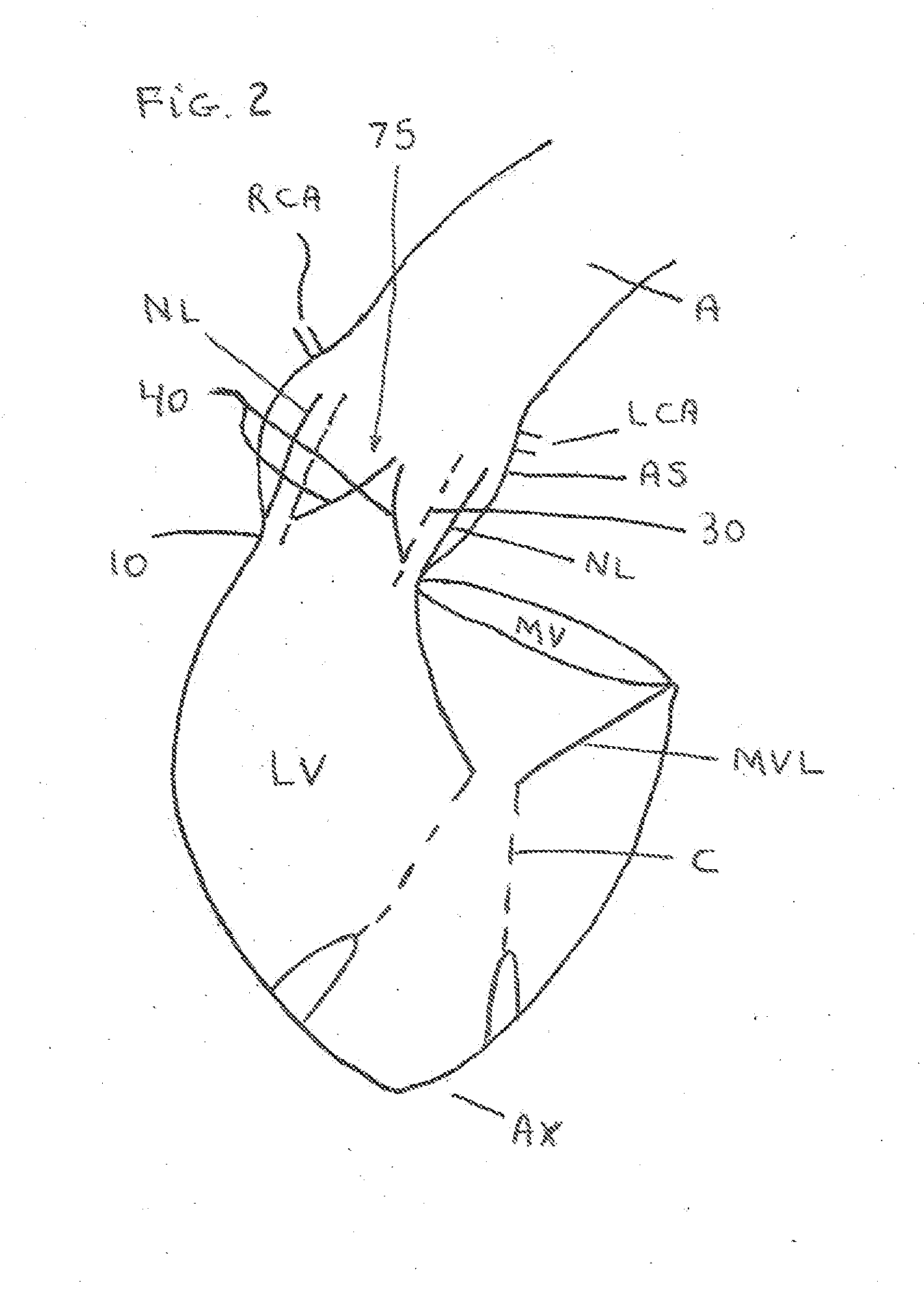
[0033]Shown in FIGS. 1A, 1B and 2 are views of a heart and the valves made through an approximate plane which very nearly passes through the fibrous rings that form the bases of attachment for the four major valves found in the heart, the mitral valve (MV), tricuspid valve (TV), aortic valve (AV) and the pulmonary valve (PV). The posterior aspect (5) of AV annulus (10) comes into an elongated contact with the anterior aspect (15) of the mitral valve (MV) ring; the aortic annulus (10) is elongated to form an oval with the annulus long axis (20) along the direction of this elongated contact extending from the right trigone (RT) to the left trigone (LT); the annulus short axis (25) is perpendicular to the annulus long axis (20).

[0034]The three native aortic valve leaflets (40) are generally positioned such that the native right anterior leaflet (RAL) is located on the anterior right aspect of the aortic annulus (10) and is closely associated with the right coronary artery (RCA). The na...


PUM


Abstract

An oval valve for use in transcutaneous aortic (TAVI) or mitral valve implantation or for direct access valve implantation. The oval leaflet frame or stent provides a better seal with the oval native annulus to reduce perivalvular leaks. The valve leaflets are a bileaflet configuration to provide improved leaflet coaptation independent of the amount of ovality of the native valve annulus. The bileaflet configuration is less dependent upon the diameter and perimeter of the native valve annulus and provides leaflet coaptation without intravalvular leakage.

Description

CROSS REFERENCE TO RELATED APPLICATIONS[0001]This patent application makes reference to and thereby incorporates all information found in issued U.S. Pat. Nos. 6,245,101 and 6,451,051 which describe aspects of stents and attachment means having hinges and struts. This patent application makes reference to and incorporates all information found in the provisional patent application No. 61 / 572,849 entitled Oval Aortic Valve, filed 22 Jul. 2011 by William J. Drasler.FIELD OF THE INVENTION[0002]This invention relates to transcatheter aortic valve implantation (TAVI) devices or direct surgical access devices that push the native aortic valve leaflets to the side and cover the native aortic valve leaflets. The TAVI devices are comprised of a stent onto which is mounted a flexible leaflet valve. The TAVI device is generally delivered via access from the femoral artery, or through apical access, through direct access into the aorta, or via other large vessels that are suitable for large cat...

Claims


Application Information

Patent Timeline
Patent Type & Authority Applications(United States)
IPC IPC(8): A61F2/06
CPCA61F2/2412A61F2230/0008A61F2/2418
Inventor DRASLER, WILLIAM JOSEPH
Owner DRASLER WILLIAM JOSEPH
Why Eureka
Try Eureka