Laser Diode Array with Fiber Optic Terminaton for Surface Treatment of Materials

a laser diode array and fiber optic termination technology, applied in the field of materials surface treatment apparatus and methods, can solve the problems of affecting process economics and efficiencies, substantial localized thermal gradients, and conventional laser beam treatment that requires substantial power, so as to achieve easy adjustment, improve relative cost, and improve operational efficiency

Active Publication Date: 2013-01-31
IPG PHOTONICS CORP
View PDF35 Cites 11 Cited by
  • Summary
  • Abstract
  • Description
  • Claims
  • Application Information

AI Technical Summary

Benefits of technology

[0008]In response, it is now recognized that the performance of the treatment process can involve irradiation with light emitted from a laser diode array or a laser diode array assembly where the incident radiation intensity stays relatively uniform over a range of spacing at the standard small NA's from the light source (fiber terminations) to a treatment surface. It is also understood that irradiation parameters can now be easily adjusted as function of desired process parameters. Relative cost, repair, and operational efficiencies are improved.
[0009]Where specific laser properties such as coherence and short pulse duration are not required, the proposed laser diode array provides distinct advantages, including; greater (two fold-plus) energy efficiency than lasers, less costly (roughly two-fold) operation, and use where large areas need to be exposed or treated.
[0010]It is also recognized that different laser diodes made from such semiconductor materials such as GaAs or InP (or other materials) can produce intense, nearly monochromatic, radiation having different absorption or “coupling efficiencies” for different materials. It is also recognized that diode characteristics can be selected for optimum coupling efficiency for a given material for treatment.

Problems solved by technology

Conventionally, this results in substantial localized thermal gradients.
Additionally, conventional laser beam treatments require substantial power, which impacts process economics and efficiencies.
Exposure can result in material property changes due to re-crystallization, or different hardness or different electrical properties after such exposure.

Method used


Image

  • Laser Diode Array with Fiber Optic Terminaton for Surface Treatment of Materials
  • Laser Diode Array with Fiber Optic Terminaton for Surface Treatment of Materials
  • Laser Diode Array with Fiber Optic Terminaton for Surface Treatment of Materials

Examples


Embodiment Construction

[0032]Reference will now be made in detail to embodiments of the invention. Wherever possible, same or similar reference numerals are used in the drawings and the description to refer to the same or like parts or steps. The drawings are in simplified form and are not to precise scale. For purposes of convenience and clarity only, directional (up / down, etc.) or motional (forward / back, etc.) terms may be used with respect to the drawings. These and similar directional terms should not be construed to limit the scope of the invention in any manner.

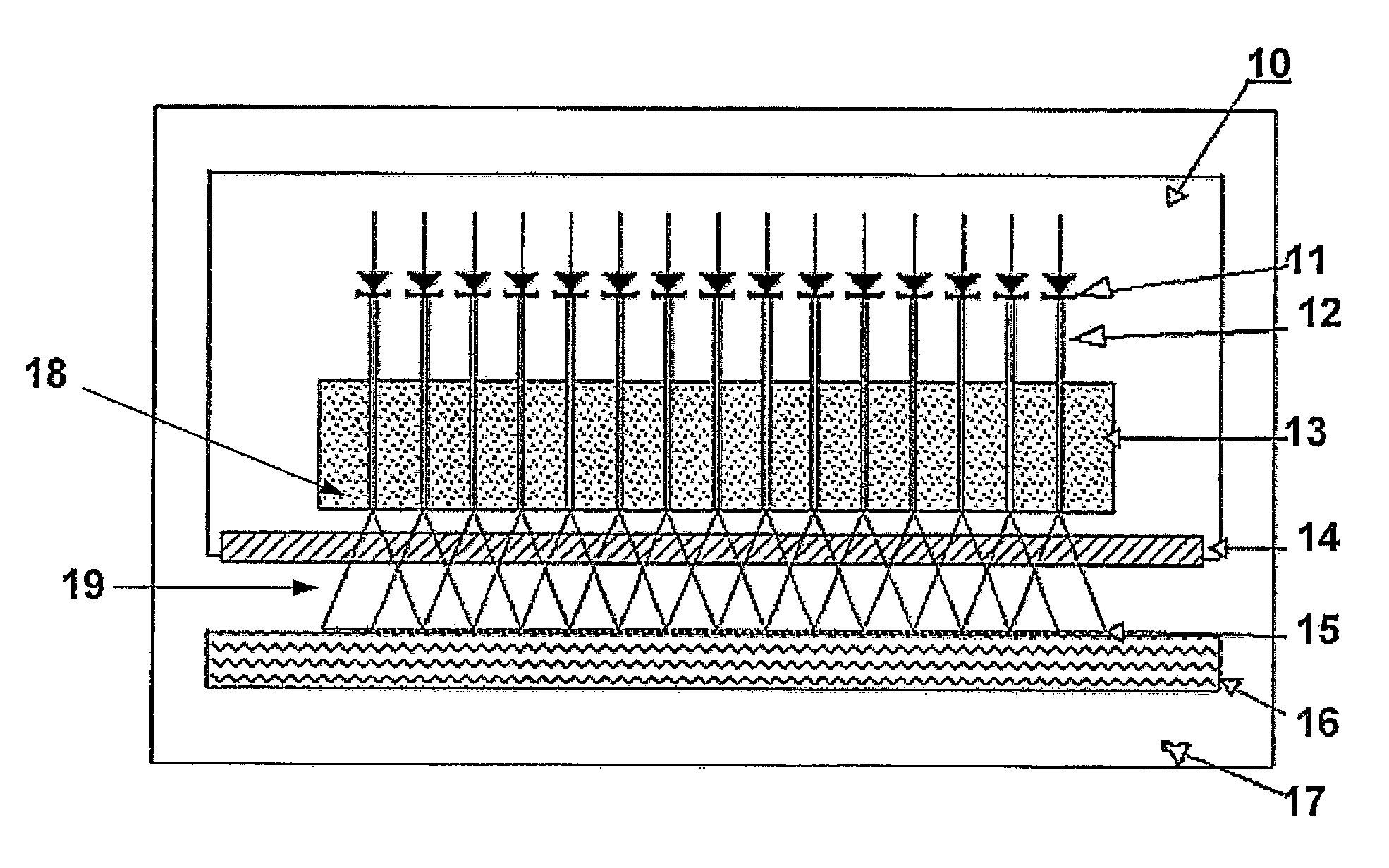
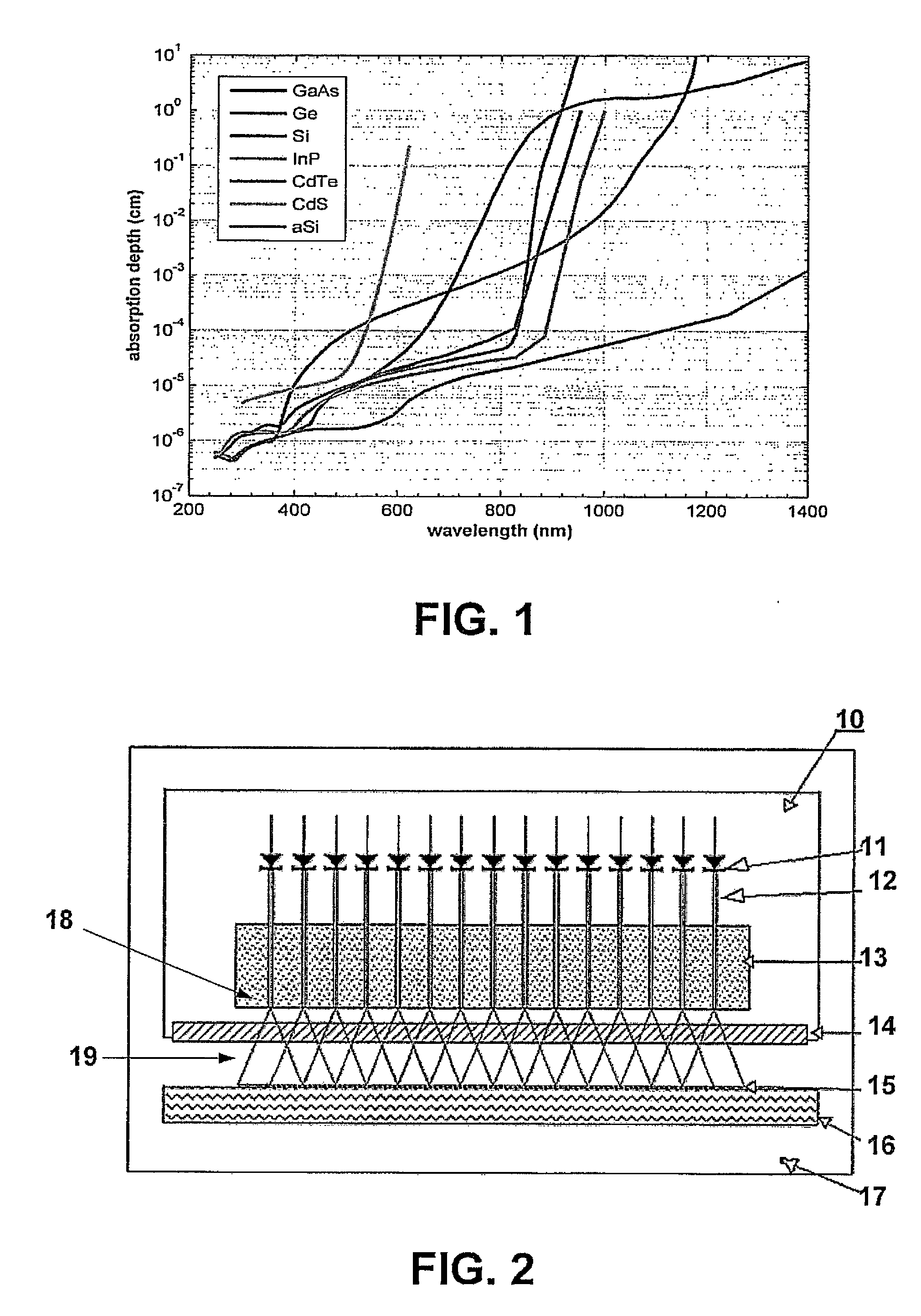
[0033]One of the present inventions is laser diode annealing of silicon wafers for solar cell manufacturing. Here the silicon wafer surface needs to be heated so that the surface temperature exceeds the melting point of Si (Silicon). Tests have shown that CW laser radiation with a wavelength of 1.070-1.080 μm (microns) at an irradiance in the region of 500-2000 W / cm2 and exposures of 50-200 J / cm2 can be used to melt the surface of a Si wafer....


PUM

PropertyMeasurementUnit
absorption depthaaaaaaaaaa
wavelengthsaaaaaaaaaa
wavelengthaaaaaaaaaa

Abstract

Individually operable laser diodes in an array are associated with optical fibers for treatment of a material. Each laser diode has a generally Gaussian or similar profile. A guide block receives optical fiber terminal distal ends and enables irradiation of a surface for treatment with overlapping profiles. A control system controls individual laser diodes to achieve desired illumination profiles for a given process. The process is performed in a suitable environment which may include a vacuum system, controlled gaseous environment, or in a doping medium such as a surface coating or even a liquid. Optional relay optics interposed between the terminal distal ends and the treatment material allows distant relaying and reimaging. An optical isolator assembly may be interposed between the relay optics and the treatment material. The system and related methods allow direct irradiation from laser diodes to treat materials.

Description

BACKGROUND OF THE INVENTION[0001]1. Field of the Invention[0002]The present invention relates to an apparatus and method for surface treatment of materials using intense direct irradiation from individually controllable high power laser diodes. More particularly, the present invention provides a laser diode array with fiber optic termination and a method enabling alteration of material properties near the surface or through the entire body of a material in a target region.[0003]2. Description of the Related Art[0004]Industrial applications of lasers involve exposing material surfaces to cause material property changes or modifications. These include applications such as hardening of metals, laser annealing, or gas immersion doping.[0005]Conventionally, an incident laser beam impinges on only a tiny part of a surface for treatment, for example a wafer, on an incident side at any moment in time. Conventionally, this results in substantial localized thermal gradients. Additionally, con...

Claims


Application Information

Patent Timeline
Patent Type & Authority Applications(United States)
IPC IPC(8): C03B37/10
CPCH01L21/67115B23K26/00
Inventor PIWCZYK, BERNHARDSHINER, WILLIAM
Owner IPG PHOTONICS CORP
Why Eureka
Try Eureka