
Establishing communication between well pairs in oil sands by dilation with steam or water circulation at elevated pressures

a technology of communication and well pair, which is applied in the field of in situ recovery processes for hydrocarbon recovery from oil sands, can solve the problems of reducing the effectiveness of long wellbore, less uniform heating, and inapplicability of solutions, and achieves the effects of increasing steam pressure, reducing steam pressure, and increasing circulation ra

Active Publication Date: 2013-02-07
FCCL PARTNERSHIP
View PDF4 Cites 34 Cited by
  • Summary
  • Abstract
  • Description
  • Claims
  • Application Information

AI Technical Summary

Benefits of technology

The present invention provides a method for establishing fluid communication between a well pair in an oil-sand reservoir. The method involves circulating steam or water within the wells to apply pressure to the oil sands and dilate them. The pressure is increased to a level sufficient to enlarge the dilated region, and then maintained until a signal indicative of fluid communication between the wells is detected. The method can be adjusted to control the bottom-hole pressure and can be used in a steam-assisted gravity drainage process. The technical effect of the invention is to provide a reliable and effective method for establishing fluid communication in oil-sand reservoirs.

Problems solved by technology

For long wells a complete formation of a steam chamber along the length of the wellbore may take several months, thereby reducing the effectiveness of the long wellbore.
Depending on reservoir characteristics, this initial communication and drainage impact early production rate and even ultimate recovery.
Increasing the ΔP can increase fluid transport and convection; however this solution is not applicable once breakthrough has occurred anywhere along the well pair.
They state that while a higher pressure difference can result in faster initialization, it can also result in less uniform heating and increasing the potential for premature steam breakthrough at the heel.
Lesage teaches that it is important not to fracture the formation because once fractured, most of the injected steam will flow into the fracture thereby making it very difficult to heat the formation along the length of the horizontal wellbore.

Method used


Image

  • Establishing communication between well pairs in oil sands by dilation with steam or water circulation at elevated pressures
  • Establishing communication between well pairs in oil sands by dilation with steam or water circulation at elevated pressures
  • Establishing communication between well pairs in oil sands by dilation with steam or water circulation at elevated pressures

Examples


example i

Standard Steam Circulation Start-Up (Comparison)

[0100]SAGD start-up was conducted with circulation of steam in each of injector and production wells at low injection pressures for three well pairs well on the same oil pad (denoted as B01) of an oil sand reservoir in Alberta, Canada. The three well pairs are denoted as B01-1, B01-2, and B01-3.

[0101]The B01 Pad was located in a thick and high reservoir quality region with a McMurray formation. The bitumen (oil sands) interval was overlain by a gas cap (˜4 m in thickness) and bottom water at the base. The production wells were at least 5 to 10 meters above the water zone at the base. The bitumen interval (30-35 meters) contained clean cross-bedded sands with an average porosity of about 33% and oil saturation of about 80%.

[0102]A standard circulation start-up procedure for SAGD start-up was used. Specifically, the well pairs were configured as illustrated in FIG. 5. Steam was injected into the inner tubing string and returns were produ...

example ii

Dilation Start-Up at B01-6

[0109]Start-up at another well pair (denoted as B01-6) on the B01 pad was conducted with water injection dilation and steam circulation dilation.

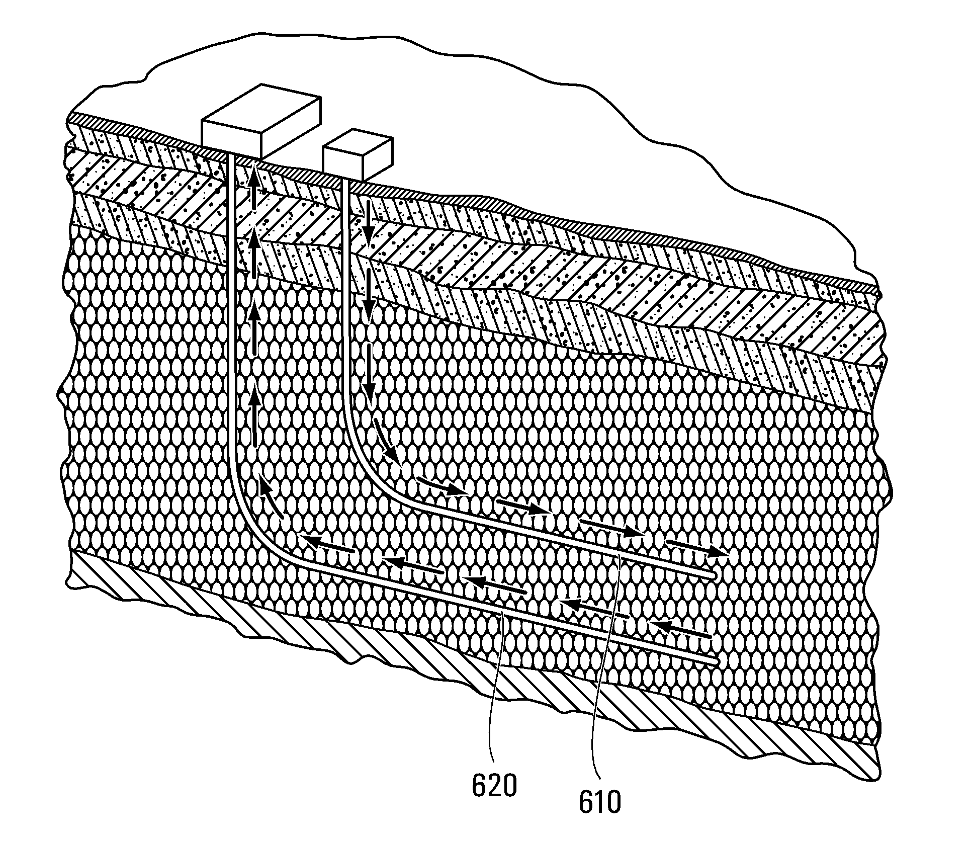
[0110]The injection and production wells were completed as illustrated in FIG. 5. In this case, the liner 612 of the injection well 610 was slotted. Further, a 6-point thermocouple coil (not shown) was inserted through inner tubing 614. The horizontal sections of the wells were about 800 m long. The vertical stress in the formation was 7.7 MPa.

[0111]The BHP and injection flow rate profiles during the start-up procedure are shown in FIGS. 7 and 8. The pressure difference between the wells at critical times is shown in FIG. 9. As shown in FIG. 9, the hydrostatic head pressure of the gas column in the well was about 3.63 MPa.

[0112]Initially, water was injected into both the injector and producer to dilate the inter-well region for 4 days. The return valves for both wells were closed so the injected water was not produ...

example iii

Dilation Start-Up at B01-5

[0121]Start-up at another well pair (denoted as B01-5) on the B01 pad was conducted with steam circulation dilation.

[0122]For the dilation start-up procedure, coiled tubing instrumentation string containing 6 thermocouple points equally spaced along the length of the liner were added to the standard well completion inside the inner tubing string of the injection well. The wells were completed as shown in FIG. 6.

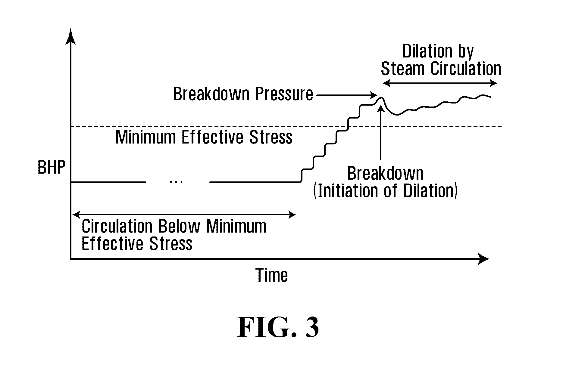
[0123]The well was initially subjected to steam circulation at steady, low BHP pressures (below or about 4 MPa) for 15 days.

[0124]Steam was then circulated in the wells at substantially steady state at pressures of about 5 MPa. Nitrogen gas was injected during this stage, which allowed direct measurement of the BHP. The BHP in each well was calculated based on the wellhead casing pressure and an estimated hydrostatic pressure gradient for nitrogen at the measured casing temperature. The measured BHP and injection rates are shown in FIGS. 12, 13, 14, ...


PUM


Abstract

A method of establishing fluid communication between a well pair in an oil-sand reservoir is provided, where dilatable oil sands in the reservoir form a barrier to fluid communication between the well pair. Steam or water is circulated within at least one well to apply a steam or water pressure to a region of the oil sands adjacent to the well. The steam or water pressure is increased to a dilation pressure sufficient to dilate the oil sands in the region. While circulating steam or water within the well at a substantially steady state, the steam or water pressure is maintained at a level sufficient to enlarge the dilated region, until detection of a signal indicative of fluid communication between the well pair. The rates of steam or water injection and production may be monitored and adjusted, and the steam or water pressure may be controlled by adjusting the rate of steam or water injection or production to vary a bottom-hole pressure in the well.

Description

CROSS-REFERENCE TO RELATED APPLICATION[0001]This application claims the benefit of, and priority from, U.S. Patent Application Ser. No. 61 / 515,539, filed Aug. 5, 2011, and entitled “Establishing Communication between Well Pairs in Oil Sands by Dilation with Steam or Water Circulation at Elevated Pressures,” the entire contents of which are incorporated herein by reference.FIELD OF THE INVENTION[0002]The present invention relates generally to in situ processes for recovering hydrocarbon from oil sands, and particularly to steam-assisted in situ recovery processes.BACKGROUND OF THE INVENTION[0003]Some subterranean deposits of viscous petroleum can be extracted in situ by lowering the viscosity of the petroleum to mobilize it so that it can be moved to, and recovered from, a production well. Reservoirs of such deposits may be referred to as reservoirs of heavy hydrocarbon, heavy oil, bitumen, tar sands, or oil sands. The in situ processes for recovering oil from oil sands typically inv...

Claims


Application Information

Patent Timeline
IPC IPC(8): E21B43/17E21B47/07
CPCE21B43/24E21B43/2406E21B43/305E21B43/18
Inventor ABBATE, JASON P.BARBER, CHADELLIOTT, CHRISTOPHER JAMESGITTINS, SIMONPOPKO, LOGANZAMAN, MALIHA
Owner FCCL PARTNERSHIP
Learn More