Electrolyte for magnesium battery

a magnesium anode and electrolyte technology, applied in the direction of non-aqueous electrolyte cells, cell components, group 3/13 element organic compounds, etc., can solve the problems of unreported compatibility with the electrolyte system, unsuitable cathode material, and inability to meet the requirements of magnesium anode cells, etc., to achieve low environmental impact and safe handling

Inactive Publication Date: 2013-02-07
TOYOTA JIDOSHA KK
View PDF3 Cites 51 Cited by
  • Summary
  • Abstract
  • Description
  • Claims
  • Application Information

AI Technical Summary

Benefits of technology

[0018]Therefore, an object of the present invention is to provide an electrolyte system which efficiently transports Mg ions, is compatible with magnesium and other battery components, including stainless steel, is safe to handle and imparts low environmental impact.

Problems solved by technology

Therefore, conventional electrolyte systems employed in lithium transport systems are not suitable for a cell having a magnesium anode.
However, a suitable cathode material, compatible with the electrolyte system was not reported.
However, these electrolyte mixtures are not likely to be of practical commercial utility due to air and moisture sensitivity characteristic of such Grignard-based materials.
Moreover, the in-situ generated electrolytes based on reaction of phenyl magnesium chloride / aluminum chloride electrolyte have limited anodic stability, and significantly, such materials are highly nucleophilic and intrinsically strong reducing agents.
This chemical reactivity character may be problematic, because to construct an electrochemical cell employing a Grignard type electrolyte, a cathode material which is essentially chemically inert to the Grignard based electrolyte may be required.
From a practical point of view, with regard to production and use of a commercial battery, electrolyte systems containing agents such as dibutyl magnesium are problematic because of corrosivity, inhalation hazard, flammability and moisture sensitivity.
However, Mg batteries cannot utilize commercially available aprotic ionic salts such as magnesium bis(trifluoromethanesulfonyl)-imide and magnesium perchlorate because of the reported formation of a solid electrolyte interface (SEI) film impermeable to Mg ions which prohibits deposition / dissolution (Feng, Z: Surface Coating Technologies, Vol 201, pp 3783-3787, 2006).

Method used


Image

  • Electrolyte for magnesium battery
  • Electrolyte for magnesium battery
  • Electrolyte for magnesium battery

Examples


examples

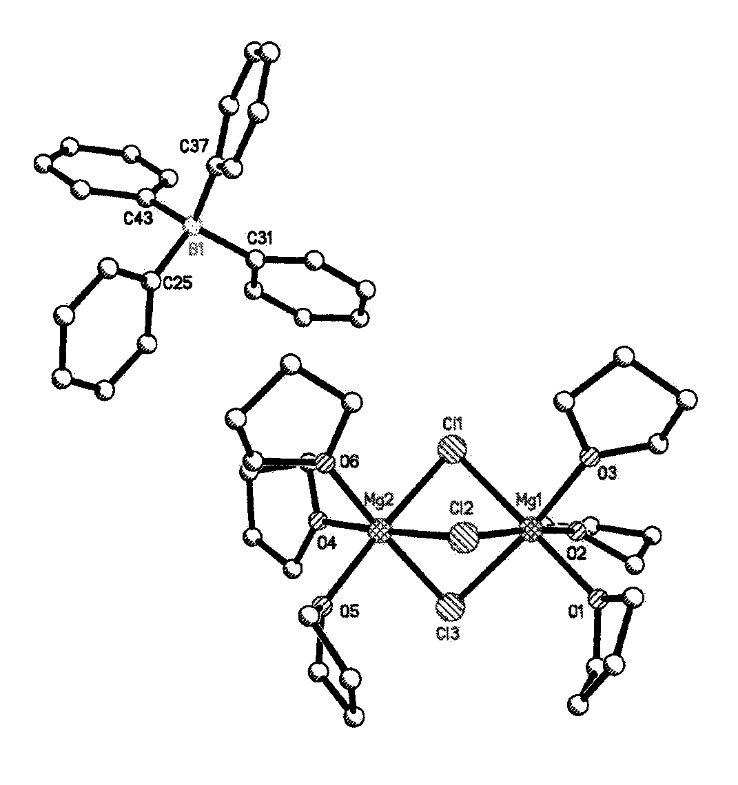
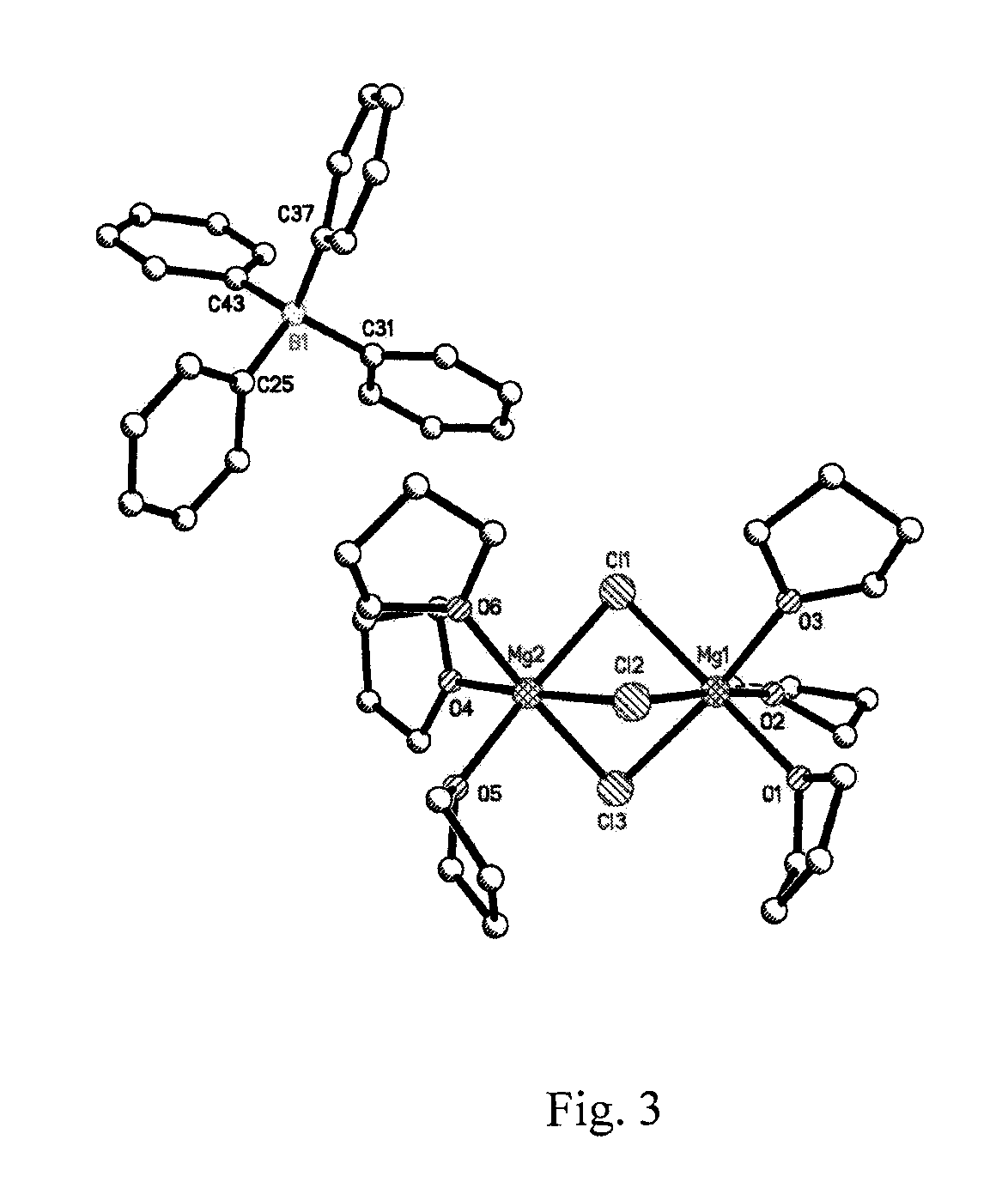
Synthesis of (Mg2(μ-Cl)3.6THF)(BPh)4 electrolyte

[0054]In an argon-filled glovebox, PhMgCl (2 M solution in THF, 3.80 mL,) was mixed with BPh3 (0.5 M solution in THF, 10 mL) in a 20 ml screw capped vial. The vial was immediately capped and vigorously stirred for 24 hours. The crystals were formed by slow diffusion of anhydrous hexane (Sigma-Aldrich, 15 mL) and were washed with hexane and dried under vacuum to furnish off white crystalline product (Mg2(μ-Cl)3.6THF)(BPh)4.

Crystal Summary of (Mg2(μ-Cl)3.6THF)(Bph4)

[0055]Crystal data for C48H68BCl3Mg2O6; Mr=906.80; Monoclinic; space group P21 / c; α=16.4151(16) Å; b=16.5787(16) Å; c=18.5617(19) Å; α=90°; β=109.3640(10)°; γ=90°; V=4765.6(8) Å3; Z=4; T=120(2) K; λ(Mo-Kα)=0.71073 Å; μ(Mo—Kα)=0.265 mm−1; dcalc=1.264 g.cm−3; 76313 reflections collected; 11872 unique (Rint=0.0351); giving R1=0.0345, wR2=0.0860 for 9917 data with [I>2σ(I)] and R1=0.0443, wR2=0.0925 for all 11872 data. Residual electron density (e−. Å−3) max / min: 1.148 / −0.351.

An a...


PUM

PropertyMeasurementUnit
energy densityaaaaaaaaaa
negative reduction potentialaaaaaaaaaa
voltageaaaaaaaaaa

Abstract

A magnesium battery, having an anode containing magnesium; a cathode stable to a voltage of at least 2.6 V relative to a magnesium reference; and an electrolyte containing an electrochemically active magnesium salt obtained by reaction of a Grignard reagent or Hauser base with a boron compound of formula BR3 is provided. The electrolyte is stable to 2.6 E.V. vs. Mg in the presence of stainless steel.

Description

BACKGROUND OF THE INVENTION[0001]1. Field of the Invention[0002]Increasing costs of traditional fuels along with high atmospheric pollution amplify the need for efficient methods of energy capture for cheap, renewable, environmentally friendly power sources. High energy density batteries are conventionally employed for energy storage and release and may be viable energy sources in the future.[0003]Lithium ion batteries have been in commercial use since 1991 and have been conventionally used as power sources for portable electronic devices. The technology associated with the construction and composition of the lithium ion battery (LIB) has been the subject of investigation and improvement and has matured to an extent where a state of art LIB battery is reported to have up to 700 Wh / L of energy density. However, even the most advanced LIB technology is not considered to be viable as a power source capable to meet the demands for a commercial electric vehicle (EV) in the future. As thi...

Claims


Application Information

Patent Timeline
Patent Type & Authority Applications(United States)
IPC IPC(8): H01M10/056C07F5/02
CPCH01M4/381H01M4/661C07F3/02H01M10/056H01M10/054Y02E60/10
Inventor MULDOON, JOHNBUCUR, CLAUDIU BOGDAN
Owner TOYOTA JIDOSHA KK
Why Eureka
Try Eureka