Light-Emitting Device and Method for Manufacturing Same

Active Publication Date: 2013-02-14
OSRAM OPTO SEMICON GMBH & CO OHG
View PDF3 Cites 14 Cited by
  • Summary
  • Abstract
  • Description
  • Claims
  • Application Information

AI Technical Summary

Benefits of technology

[0037]According to a first aspect of the present invention, because the wavelength conversion part is formed of the light-transmissive ceramic layer, heating of the light-emitting element and the phosphor will not cause coloring or the like, nor will other factors, and long-term use becomes possible. Further, because a thickening effect imparted by the layered silicate mineral and the inorganic particulate will suppress settling of the phosphor within the mixture forming the ceramic layer, the phosphor can be dispersed in the ceramic layer in a substantially uniform manner, and the occurrence of color unevenness in the light-emitting device can be effectively suppressed. Also, because the ceramic layer contains the layered silicate mineral and the inorganic particulate, the strength of the ceramic layer is also improved.
[0038]In a second aspect of the present invention, which comprises the light-emitting device of the first aspect as mentioned above, a layered silicate mineral content of the ceramic layer of 0.5 to 20 wt % makes it possible to adequately increase the viscosity of the mixture prior to heating and to suppress settling of the phosphor.
[0039]In a third aspect of the present invention, which comprises the light-emitting device of the second aspect as mentioned above, a layered sili

Problems solved by technology

However, the specific gravity of the phosphor is greater than that of the transparent resin, and accordingly there is sett

Method used


Image

  • Light-Emitting Device and Method for Manufacturing Same
  • Light-Emitting Device and Method for Manufacturing Same
  • Light-Emitting Device and Method for Manufacturing Same

Examples


working example 1

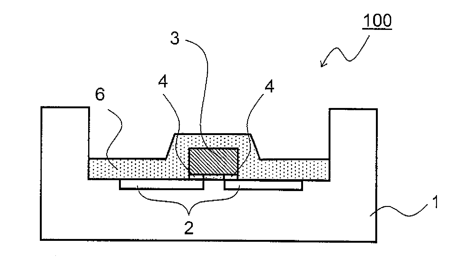
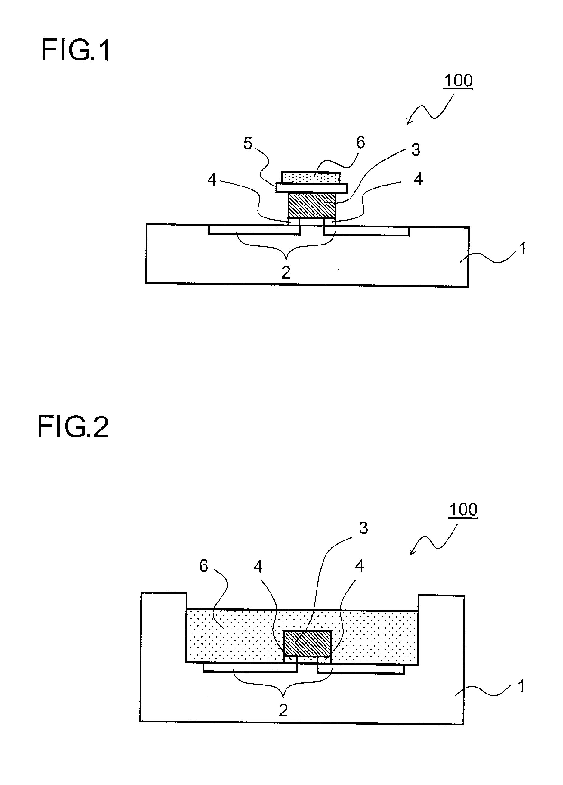
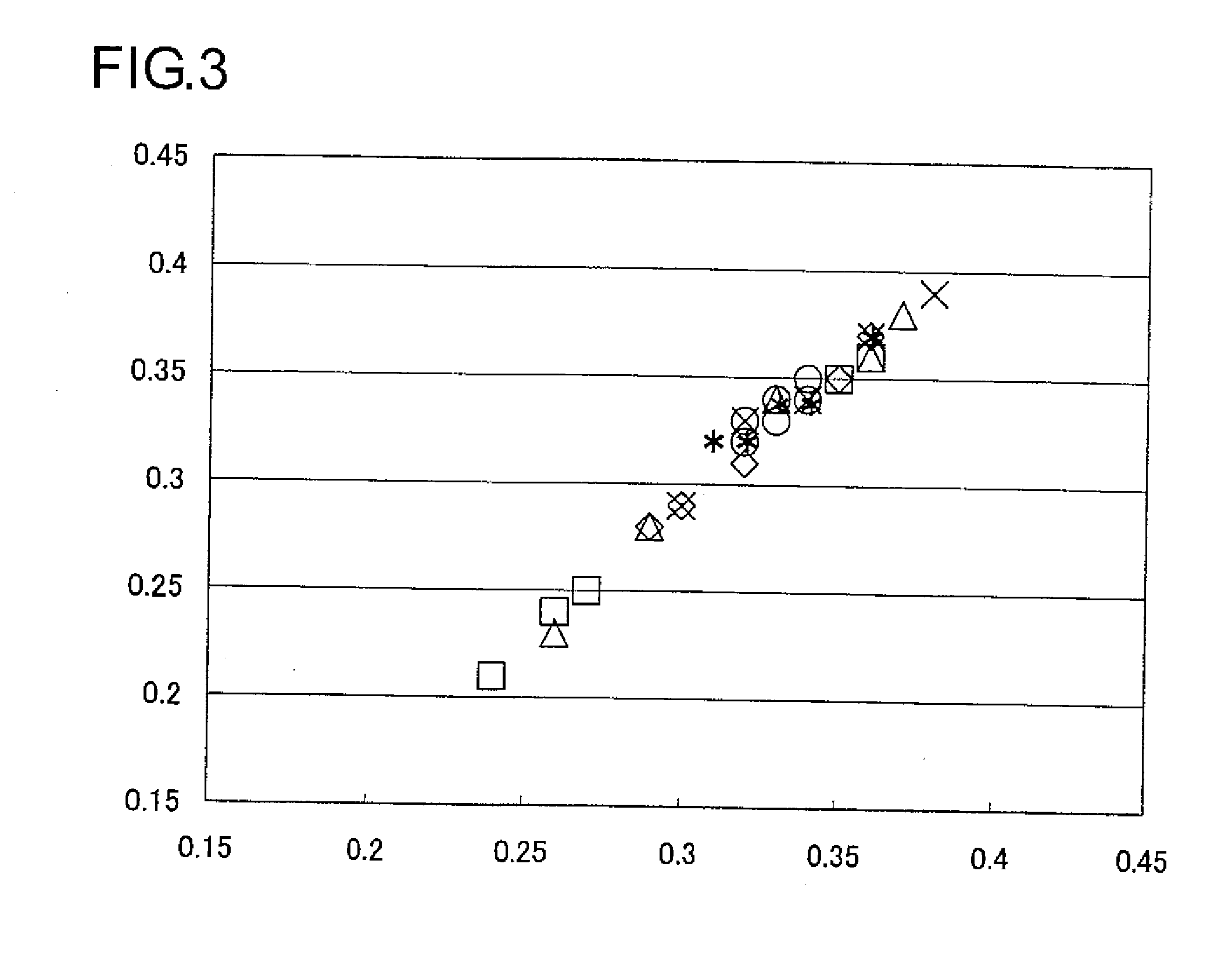
[0105]0.02 g lipophilic, surface-treated smectite (Lucentite SPN, manufactured by Co-op Chemical) was mixed and dispersed into 1 g of a polysiloxane dispersion (14 wt % polysiloxane and 86 wt % isopropyl alcohol). 0.6 g of the phosphor prepared in the preparation example described above, 0.03 g silicon oxide particulate having a median diameter (D50) of 25 nm (NanoTek Powder, manufactured by CIK NanoTek), and 0.45 g pure water were mixed into this dispersion, thus preparing a mixture.

[0106]The mixed amounts of polysiloxane, smectite, phosphor, and silicon oxide particulate were determined such that the sum of the percentages by weight within the ceramic layer after heating and polymerization would reach 100 wt % (the same also applies to working examples 2 to 11 and comparative examples 1 to 7 described below).

working example 2

[0107]A mixture was prepared by a method similar to that of working example 1, except in that the mixed amount of the phosphor was 1.1 g and the mixed amount of the pure water was 0.38 g.

working example 3

[0108]0.01 g lipophilic, surface-treated smectite (Lucentite SPN, manufactured by Co-op Chemical) was mixed and dispersed into 1 g of a polysiloxane dispersion (14 wt % polysiloxane and 86 wt % isopropyl alcohol). 0.7 g of the phosphor prepared in the preparation example described above, 0.03 g of silicon oxide particulate having a particle size distribution of 1 to 24 μm and a median diameter (D50) of 3 μm (Hi-Silica F3, manufactured by Nitchitsu), and 0.07 g of pure water were mixed into this dispersion, thus preparing a mixture.


PUM

PropertyMeasurementUnit
Temperatureaaaaaaaaaa
Thicknessaaaaaaaaaa
Viscosityaaaaaaaaaa

Abstract

A light-emitting device (100) is provided with a metal part (2) atop a planar LED substrate (1), and an LED element (3) is disposed atop the metal part (2). A glass substrate (5) is provided to an upper surface of the LED element (3), and a wavelength conversion part (6) is formed on an upper surface of the glass substrate (5). The wavelength conversion part (6) comprises a light-transmissive ceramic layer formed by heating a mixture containing a phosphor, an organometallic compound, a layered silicate mineral, an inorganic particulate, an organic solvent, and water.

Description

TECHNICAL FIELD[0001]The present invention relates to a light-emitting device having a light-emitting element as well as a wavelength conversion part including a phosphor for converting the wavelength of light emitted from the light-emitting element.BACKGROUND ART[0002]In recent years there has been increasingly widespread use of a technique for obtaining white light-emitting diodes (LEDs) by arranging an yttrium aluminum garnet (YAG) phosphor or other type of phosphor in the vicinity of a gallium nitride (GaN)-based blue LED chip, and color-mixing the blue light emitted from the blue LED chip and yellow light emitted by secondary emission upon the phosphor receiving the blue light.[0003]With a white LED of such description, there is generally employed a method for using a transparent resin throughout which the phosphor has been dispersed, to seal in an LED chip and / or a mounting part. However, the specific gravity of the phosphor is greater than that of the transparent resin, and a...

Claims


Application Information

Patent Timeline
IPC IPC(8): H01L33/00C09K11/08
CPCC09K11/7774H01L33/501H01L2933/0041C04B35/44C04B35/50C04B2235/3224B82Y30/00C04B2235/3418C04B2235/349C04B2235/483C04B2235/5436C04B2235/5454C04B2235/9646C04B2235/3225H01L2224/16
Inventor HATANO, TAKUJIADACHI, HITOSHIWASHIZU, TAKASHITAGUCHI, YOSHIHITO
Owner OSRAM OPTO SEMICON GMBH & CO OHG
Why Eureka
Try Eureka