Sintered alloy and manufacturing method thereof

Inactive Publication Date: 2013-03-07
HITACHI POWDERED METALS COMPANY
View PDF2 Cites 12 Cited by
  • Summary
  • Abstract
  • Description
  • Claims
  • Application Information

AI Technical Summary

Benefits of technology

[0019]The sintered alloy of the present invention is suitable for a turbo component for turbocharger, and has the phase A containing precipitated metallic carbides with an average particle diameter of 10 to 50 μm and the phase B containing precipitated metallic carbides with an average particle diameter of 10 μm or less so as to exhibit the metallic structure such that the phase A is rando

Problems solved by technology

However, since the sintered component disclosed in Patent document No. 1 is formed through liquid phase-sintering, the sintered component may be machined as the case of severe dimensional accuracy.
Since the large amount of hard carbides are precipitated in the sintered component, the machinability of the sintered component is not good and thus required to be improved.
I

Method used


Image

  • Sintered alloy and manufacturing method thereof
  • Sintered alloy and manufacturing method thereof
  • Sintered alloy and manufacturing method thereof

Examples


Example

Example 1

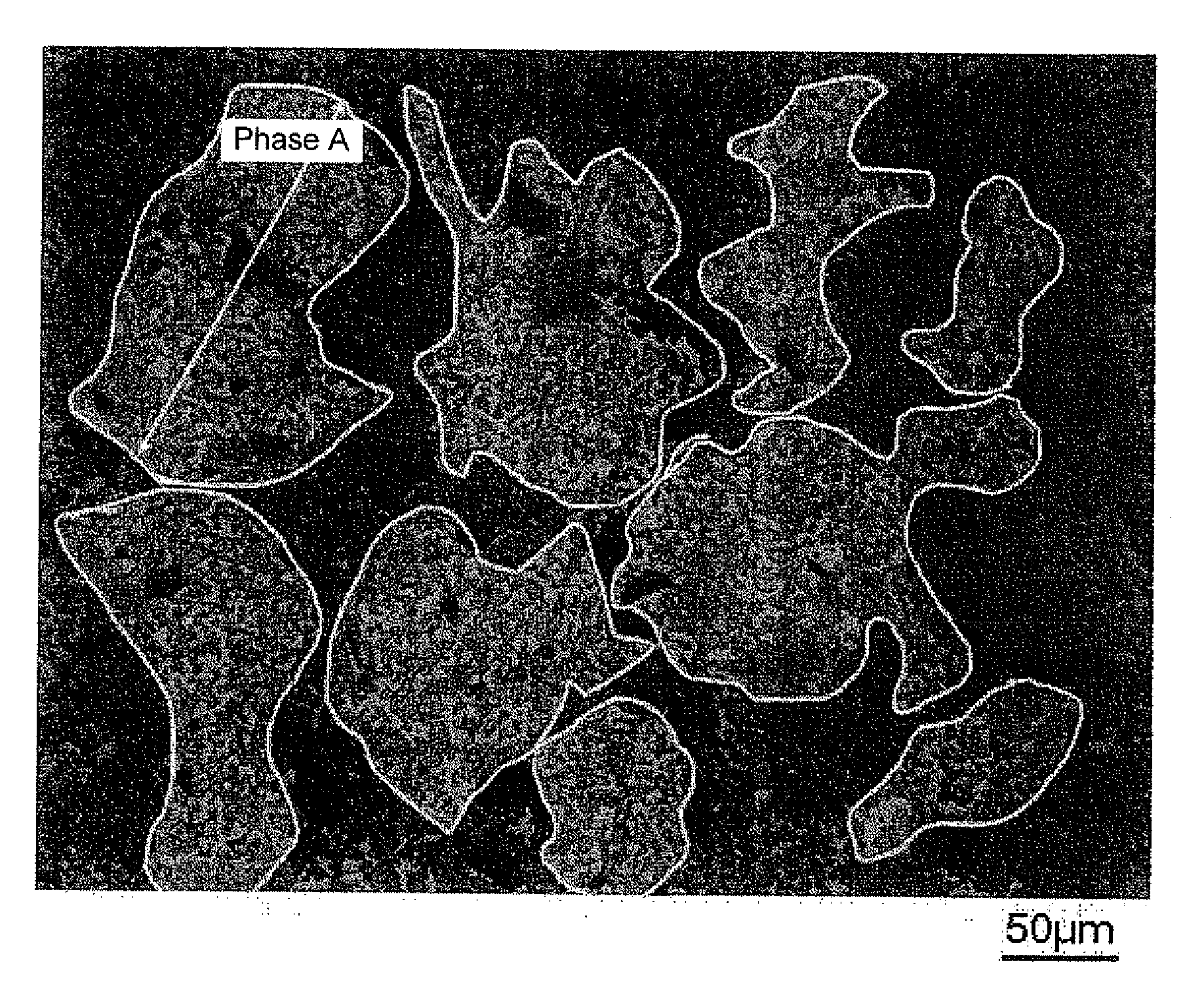
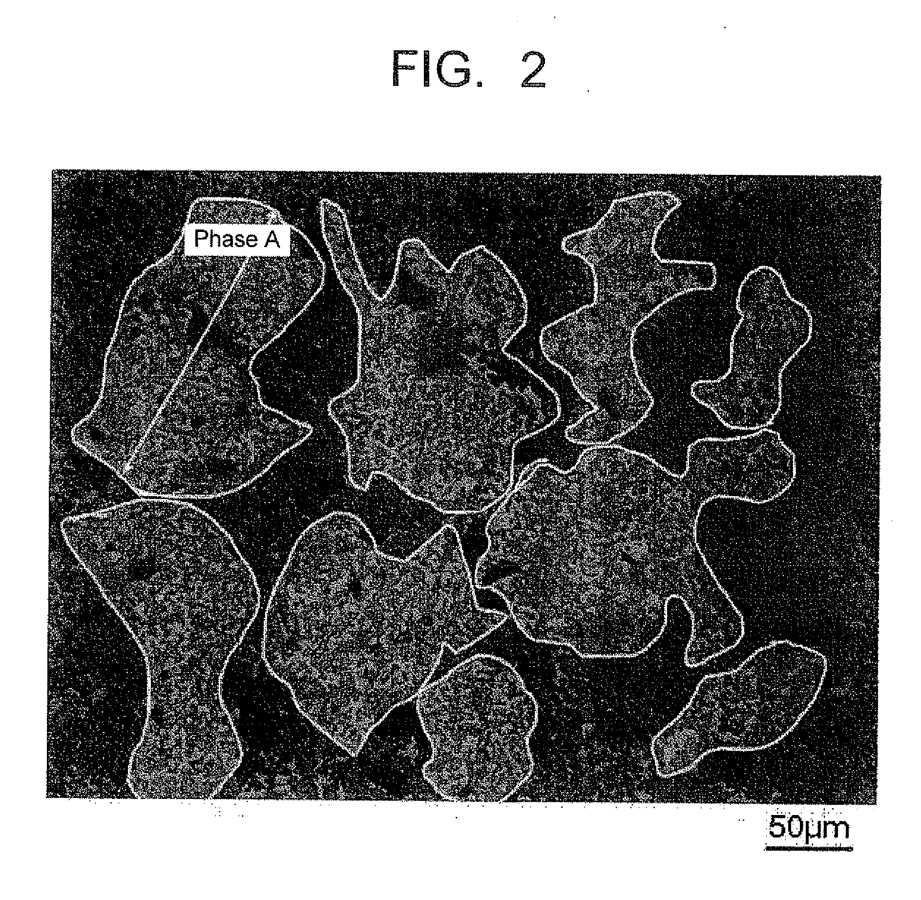
[0058]The iron alloy powder A including, in percentage by mass, Cr: 34, Ni: 10, Si: 2, C: 2 and the balance of Fe plus unavoidable impurities, the iron alloy powder B including, in percentage by mass, Cr: 18, Ni: 8 and the balance of Fe plus unavoidable impurities, the iron-phosphorus powder including, in percentage by mass, P: 20 and the balance of Fe plus unavoidable impurities, the nickel powder and the graphite powder were prepared and mixed with one another at the ratios shown in Table 1 to blend the raw material powder. The raw material powder was compressed in the shape of pillar with an outer diameter of 10 mm and a height of 10 mm and in the shape of thin plate with an outer diameter of 24 mm and a height of 8 mm, and then sintered at a temperature of 1100° C. under non-oxidizing atmosphere to form sintered samples indicated by numbers of 01 to 11. The composition in each of the sintered samples was listed in Table 1 with the aforementioned ratios of the material p...

Example

Example 2

[0070]The iron alloy powders A having the respective components shown in Table 3 were prepared, and mixed with the iron alloy powder B, the iron-phosphorus alloy powder, the nickel powder and the graphite powder which were used in Example 1 at the ratios shown in Table 3 to blend the respective raw material powder. The thus obtained raw material powder was compressed and sintered in the same manner as in Example 1 to form sintered samples 12 to 30 in the shape of pillar and in the shape of thin plate. The total components of the sintered samples were listed in Table 3. With respect to the sintered samples, the average particle diameters of carbides in the phase A and the phase B, the ratio of the phase A, the maximum dimension of the phase A, the thermal expansion coefficients, the increases in weight after oxidizing test and the abrasion depths after roll-on-disc abrasion test were measured in the same manner as in Example 1. The results were listed in Table 4 with the res...

Example

Example 3

[0085]The iron alloy powders B having the respective compositions shown in Table 5 were prepared, and mixed with the iron alloy powder A, the iron-phosphorus alloy powder, the nickel powder and the graphite powder which were used in Example 1 at the ratios shown in Table 5 to blend the respective raw material powder. The thus obtained raw material powder was compressed and sintered in the same manner as in Example 1 to form sintered samples 31 to 41 in the shape of pillar and in the shape of thin plate. The compositions of the sintered samples were listed in Table 5. With respect to the sintered samples, the average particle diameters of carbides in the phase A and the phase B, the ratio of the phase A, the maximum dimension of the phase A, the thermal expansion coefficients, the increases in weight after oxidizing test and the abrasion depths after roll-on-disc abrasion test were measured in the same manner as in Example 1. The results were listed in Table 6 with the resul...


PUM

PropertyMeasurementUnit
Temperatureaaaaaaaaaa
Lengthaaaaaaaaaa
Lengthaaaaaaaaaa

Abstract

A sintered alloy includes, in percentage by mass, Cr: 11.75 to 39.98, Ni: 5.58 to 24.98, Si: 0.16 to 2.54, P: 0.1 to 1.5, C: 0.58 to 3.62 and the balance of Fe plus unavoidable impurities; a phase A containing precipitated metallic carbides with an average particle diameter of 10 to 50 μm; and a phase B containing precipitated metallic carbides with an average particle diameter of 10 μm or less, wherein the phase A is randomly dispersed in the phase B and the average particle diameter DA of the precipitated metallic carbides in the phase A is larger than the average particle diameter DB of the precipitated metallic carbides of the phase B.

Description

CROSS-REFERENCE TO RELATED APPLICATION[0001]This application is based upon and claims the benefit of priority from the prior Japanese Patent Application No. 2011-195087 filed on Sep. 7, 2011; the entire contents which are incorporated herein by reference.BACKGROUND[0002]1. Field of the Invention[0003]The present invention relates to a sintered alloy which is suitable for a turbo component for turbocharger, particularly a nozzle body and the like which require heat resistance, corrosion-resistance and wear-resistance, and a method for manufacturing the sintered alloy.[0004]2. Background of the Invention[0005]Generally, in a turbocharger provided in an internal combustion engine, a turbine is rotatably supported by a turbine housing connected with an exhaust manifold of the internal combustion engine and a plurality of nozzle vanes are rotatably supported so as to surround the periphery of the turbine. An exhaust gas flowed in the turbine housing is flowed in the turbine from the outs...

Claims


Application Information

Patent Timeline
IPC IPC(8): B32B15/02B22F3/12B22F1/05
CPCB32B15/02C22C33/0207C22C33/0285C22C1/03C22C38/58C22C38/02C22C38/34C22C38/40C22C38/002B22F1/05B22F3/16
Inventor FUKAE, DAISUKEKAWATA, HIDEAKI
Owner HITACHI POWDERED METALS COMPANY
Why Eureka
Try Eureka