Liquid-gas interface plasma device

Active Publication Date: 2013-03-07
COLORADO STATE UNIVERSITY
View PDF3 Cites 10 Cited by
  • Summary
  • Abstract
  • Description
  • Claims
  • Application Information

AI Technical Summary

Benefits of technology

[0006]Plasmas have broad applicability to provide alternative solutions to industrial, scientific and medical needs, especially workpiece surface processing at low temperature. Plasmas may be delivered to a workpiece, thereby affecting multiple changes in the properties of materials upon which the plasmas impinge. Plasmas have the unique ability to create large fluxes of radiation (e.g., ultraviolet), ions, photons, electrons and other excited-state (e.g.

Problems solved by technology

In addition, use of high levels of hydrogen peroxide raises patient safety concerns.
High concentration of hydrogen peroxide results in incr

Method used


Image

  • Liquid-gas interface plasma device
  • Liquid-gas interface plasma device
  • Liquid-gas interface plasma device

Examples


Example

Example 1

Bone Etching

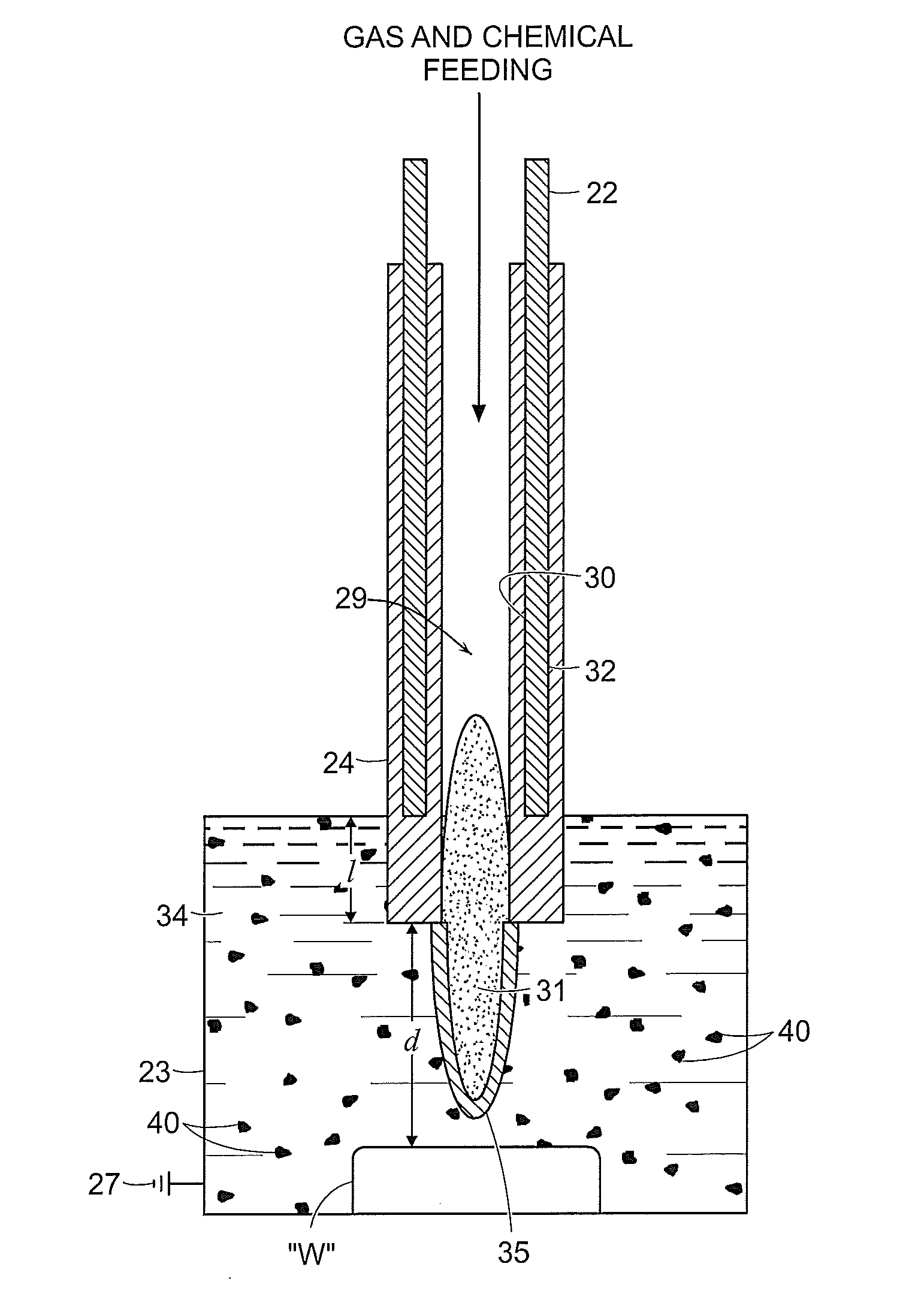
[0081]FIGS. 8A and 8B illustrate the effect of the above-discussed plasma effluent on bone tissue supplied thereto in a liquid environment. In each example, bone tissue was submerged in deionized water and NaCl was added to the water to provide chloride ions (e.g., from NaCl) as a chemical precursor for forming localized lesions. The electrode was submerged into the liquid and plasma generation was initiated and maintained for two (2) minutes. The lesion in FIG. 7A was formed using an electrode having a distal portion that is submerged to the submersion distance “d” of larger than 2 mm, whereas FIG. 7B shows the effects formed by an electrode having a distal portion submerged to the submersion distance “d” of less than 2 mm. The effects of using smaller “d” are more pronounced as illustrated in FIG. 7B, which shows charring and other tissue removal due to the hotter temperature developed at the plasma effluent. The plasma effluent produced by the device at a sha...

Example

Example 2

Tooth Whitening

[0083]FIG. 10 illustrates the effectiveness of the above-discussed plasma on tooth whitening. FIG. 10 shows six photographs of a tooth taken prior to treatment and at various points in the treatment process, namely, at one, two, three, four and eight minutes. The tooth was submerged in deionized water and the electrode was brought in proximity with the tooth (e.g., submerged into the liquid). Argon gas was supplied to the plasma device and plasma generation was initiated and maintained for eight minutes. The photos illustrate the gradual progression of the treatment process and complete removal of the stain from the tooth.

[0084]FIGS. 11A and 11B illustrate enlarged photos of the tooth. FIG. 11A shows the tooth at ×170 magnification illustrating the plasma treated region and a non-treated region and FIG. 11B shows the tooth at ×750 magnification in the treated region. The plasma-treated region shows a relatively smooth surface when compared with the non-treate...

Example

Example 3

Catalysts in Liquid Media

[0086]Titanium oxide (TiO2) catalysts were added into deionized water and plasma was generated within the water medium. The effectiveness of TiO2 catalysts was measured by spectroscopy of hydroxyl (OH) and hydrogen (H) radicals, namely, H beta and H alpha radicals. As illustrated in FIGS. 13-15, which show the comparison of measured intensity for the hydroxyl, H beta and H alpha radicals were generated in deionized water and deionized water having nanoparticles of TiO2. The increased intensity is indicative of a higher concentration of the radicals, which are attributed to the addition of the catalysts.

[0087]FIG. 16 shows the absorption of methylene blue in pure deionized water and in deionized water including nanoparticles of TiO2. Methylene blue is a common indicator chemical of hydroxyl radicals since methylene blue reacts with hydroxyl radicals, which causes a change in color from blue to clear. The sample with nanoparticles had a lower absorpti...


PUM


Abstract

A method for whitening teeth is disclosed. The method includes supplying a liquid sufficient to at least partially submerge a portion of a tooth; positioning a plasma device adjacent to the submerged portion of the tooth; supplying ionizable media to the plasma device; and igniting the ionizable media at the plasma device sufficient to form a plasma effluent in the presence of the liquid at the distal portion, whereby the plasma effluent reacts with the liquid to form at least one reactive species that interacts selectively with foreign matter disposed on the tooth.

Description

CROSS-REFERENCE TO RELATED APPLICATION[0001]The present application claims the benefit of and priority to International Application No. PCT / US2010 / 029485 filed by Koo et al. on Mar. 31, 2010, which is a continuation and claims the benefit and priority to International Application No. PCT / US2009 / 045708 filed by Moore et al. on May 29, 2009, which claims the benefit of and priority to U.S. Provisional Application Ser. No. 61 / 057,667 entitled “PLASMA-BASED CHEMICAL SOURCE DEVICE AND METHOD OF USE THEREOF” filed by Moore et al. on May 30, 2008, the entire contents of all of which are incorporated by reference herein.BACKGROUND[0002]1. Technical Field[0003]The present disclosure relates to plasma devices and processes for surface processing and material removal or deposition. More particularly, the disclosure relates to an apparatus and method for generating and directing chemically reactive, plasma-generated species in a plasma device along with excited-state species (e.g., energetic ph...

Claims


Application Information

Patent Timeline
IPC IPC(8): A61C17/00
CPCA61C19/06A61C19/066H05H1/2406
Inventor KOO, IL-GYOCHOI, MYEONG YEOLCOLLINS, JEREMIAH H.MOORE, CAMERON A.RAHMAN, ABDURCOLLINS, GEORGE J.
Owner COLORADO STATE UNIVERSITY
Why Eureka
Try Eureka