
METHOD OF JOINING PARTS MADE OF SiC-BASED MATERIALS BY NON-REACTIVE BRAZING WITH ADDITION OF A REINFORCEMENT. BRAZING COMPOSITIONS AND JOINT AND ASSEMBLY THAT ARE OBTAINED BY SUCH A METHOD

Inactive Publication Date: 2013-03-14
COMMISSARIAT A LENERGIE ATOMIQUE ET AUX ENERGIES ALTERNATIVES
View PDF2 Cites 22 Cited by
  • Summary
  • Abstract
  • Description
  • Claims
  • Application Information

AI Technical Summary

Benefits of technology

The invention relates to a brazing method for joining silicon carbide-based materials that allows for good mechanical adhesion at high temperatures of over 500°C and possibly reaching 850°C. The brazing temperature range of 1020°C to 1150°C allows for the brazing of materials that cannot withstand higher temperatures. The method also ensures excellent wetting of the surfaces, allowing for capillary brazing and the formation of strong joints even for thicker joints. The braze alloy does not react with the silicon carbide-based substrates, resulting in no complex, porous weakening zones at the interface.

Problems solved by technology

It is known that it is difficult to fabricate parts of large size made of ceramic, in particular made of SiC.
The tolerances after sintering the primary components in silicon carbide of large size are ill controlled and the machining of these components is unacceptable for cost-related reasons.
In addition, and for the same reasons, it is generally difficult to fabricate parts of complex shape with silicon-based compounds such as silicon carbide.
The assemblies thus obtained cannot be impervious.
The mechanical strength is only ensured by the staples and screws, which is limited.
Additionally, conventional joining techniques by welding having recourse to an energy beam with or without a filler metal (TIG, electron or laser welding) and involving the partial melting of the parts to be joined cannot be used for assembling ceramics since it is not possible to melt a substrate or a part in ceramic, and in particular since silicon carbide decomposes before melting.
In addition, the method is prohibitive from a mechanical viewpoint since it requires placing under compression porous, fragile substrates and materials such as silicon carbide composites which risk being highly damaged under this mechanical compressive loading.
In other words, solid phase diffusion bonding and joining by sintering have the disadvantage of being restrictive from an implementation standpoint since:for solid phase diffusion bonding, the shape of the parts must remain simple if uniaxial pressing is used, or else it requires complex tooling and preparation for example entailing the fabrication of a jacket, vacuum sealing, hot isostatic pressing, final machining of the jacket if HIP is used (Hot Isostatic Pressing).for co-sintering or joining by sintering the problems remain the same (shape of the parts, complex implementation) with, in addition, the need to control the sintering of a filler powder to be inserted between the two materials to be joined.these two techniques additionally require the use of long hold times (one to several hours) at high temperature since the processes used have recourse to solid state diffusion.
Parts of complex shape can be prepared using brazing, and brazing operations are limited to placing between the parts to be joined, or in the vicinity of the joint between the two parts, a filler alloy called a braze alloy and melting this alloy which is capable of wetting and spreading over the interfaces to be joined, filling the joint between the parts.
Most brazing compositions for parts in silicon carbide-based materials are insufficiently refractory.
Also, most chemical elements which form part of these metal brazing compositions are highly reactive with silicon carbide on and after 500° C. and lead to fragile compounds.
This criterion of non-reactivity or very low reactivity is not a sufficient condition however for guaranteeing good mechanical strength of the brazed joints.
The properties, in particular mechanical properties, of a silicon-based brazing composition are fully unpredictable and absolutely cannot be inferred from the mechanical properties of already known Si-based brazing compositions, even if of very close type.
In other words, when it is sought to prepare a silicon-based brazing composition in particular for brazing parts in SiC, it is absolutely not possible to refer to the mechanical properties which may be acceptable exhibited by other known Si-based brazing compositions, since any modification, however small, of a Si-based brazing composition whether concerning the type of the metal(s) brazed with the silicon or the proportions thereof, may lead to unpredictable, unexpected even major changes in the properties of the composition and in particular its mechanical properties.
The efficacy of this joining method requires brazing temperatures higher than 1300° C. for thermodynamic destabilization of the passivating silicon oxide layers which occur spontaneously on the silicon carbide surfaces, since these silicon oxide layers are detrimental to wetting by the brazing composition, even if brazing is conducted in a vacuum.
Therefore the above-mentioned brazing alloys with high silicon content and used at a temperature higher than 1300° C. are not suitable for the brazing of substrates in silicon carbide-based materials whose properties are degraded after exposure to 1300° C., even more so for those which degrade at 1150° C., even 1100° C. or lower.
However, the mechanical strength of the joint obtained with this composition (ultimate tensile strength of 375 p.s.i.—i.e. about 2.6 MPa) is very low despite the non-reactivity of this composition mentioned in document [5].
This mechanical strength is insufficient for numerous applications and in particular the main applications concerned herein, despite the low reactivity of this brazing composition with SiC.
No mechanical test result on this alloy is provided which means that good mechanical strength of the brazing can in no way be guaranteed.
Document [2] proposes (Example 3) a Pt—Si alloy which is brazed at 1200° C. The Pt content of this brazing composition is very high (77 weight % Pt), which leads to a very costly process.
This disadvantage is prohibitive for the obtaining of large-size brazed parts.
1) the brazing composition must allow a strong bond to be obtained between the two parts in silicon carbide-based material, which necessitates a non-reactive brazing composition i.e. chemically compatible with silicon carbide, and which does not form fragile compounds therewith. However, the non-reactivity does not guarantee the forming of a strong bond since this remains unpredictable. Non-reactivity is a condition for obtaining a strong bond but it is not sufficient. For example, the Fe—Si system cited in the literature [3] is non-reactive but its mechanical strength is very weak;
2) the brazing composition must obtain good wetting of the silicon carbide and good adhesion thereto. This very good wetting is essential for the quality of the joints since it notably ensures good filling quality of the joint, but it does not allow guaranteed good mechanical behaviour since this latter property is unpredictable;
3) the brazing composition must be compatible with all heating devices in particular rapid and / or localised heating devices;
4) the brazing composition must allow the formation of joints having good mechanical strength;
5) the brazing composition must be formed of a limited number of elements to facilitate the preparation and implementation thereof;
6) the brazing composition must not contain costly elements such as precious metals.

Method used


Image

  • METHOD OF JOINING PARTS MADE OF SiC-BASED MATERIALS BY NON-REACTIVE BRAZING WITH ADDITION OF A REINFORCEMENT. BRAZING COMPOSITIONS AND JOINT AND ASSEMBLY THAT ARE OBTAINED BY SUCH A METHOD
  • METHOD OF JOINING PARTS MADE OF SiC-BASED MATERIALS BY NON-REACTIVE BRAZING WITH ADDITION OF A REINFORCEMENT. BRAZING COMPOSITIONS AND JOINT AND ASSEMBLY THAT ARE OBTAINED BY SUCH A METHOD
  • METHOD OF JOINING PARTS MADE OF SiC-BASED MATERIALS BY NON-REACTIVE BRAZING WITH ADDITION OF A REINFORCEMENT. BRAZING COMPOSITIONS AND JOINT AND ASSEMBLY THAT ARE OBTAINED BY SUCH A METHOD

Examples


example 1

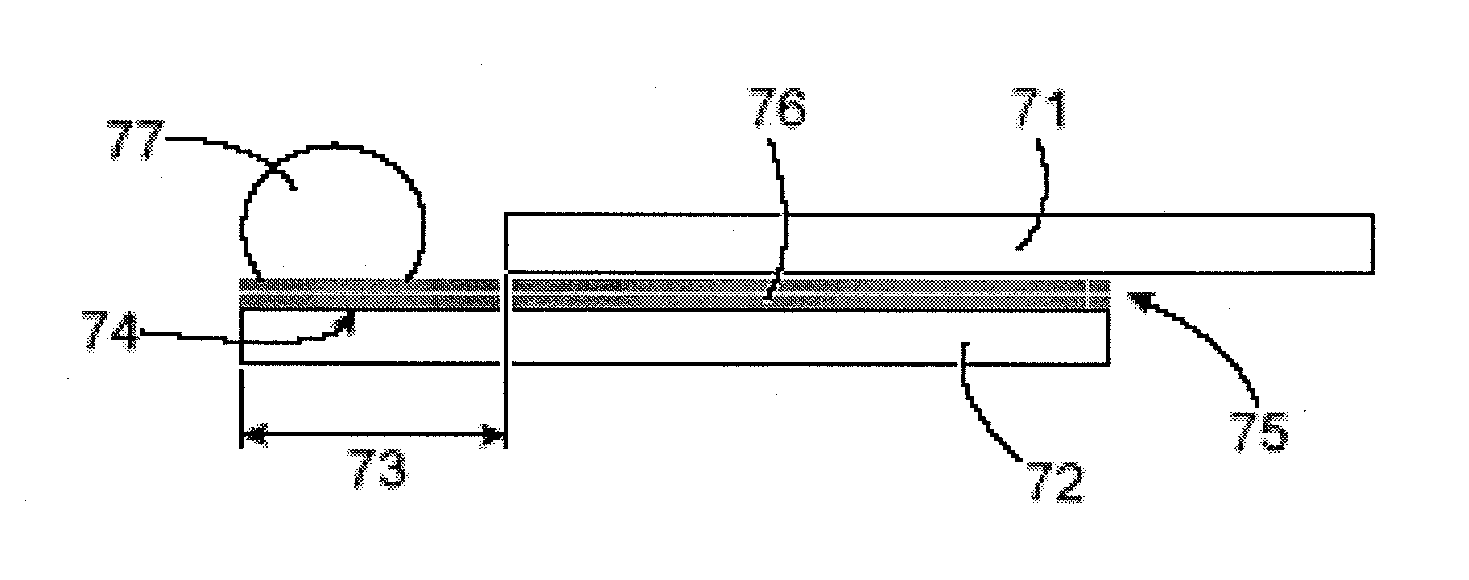
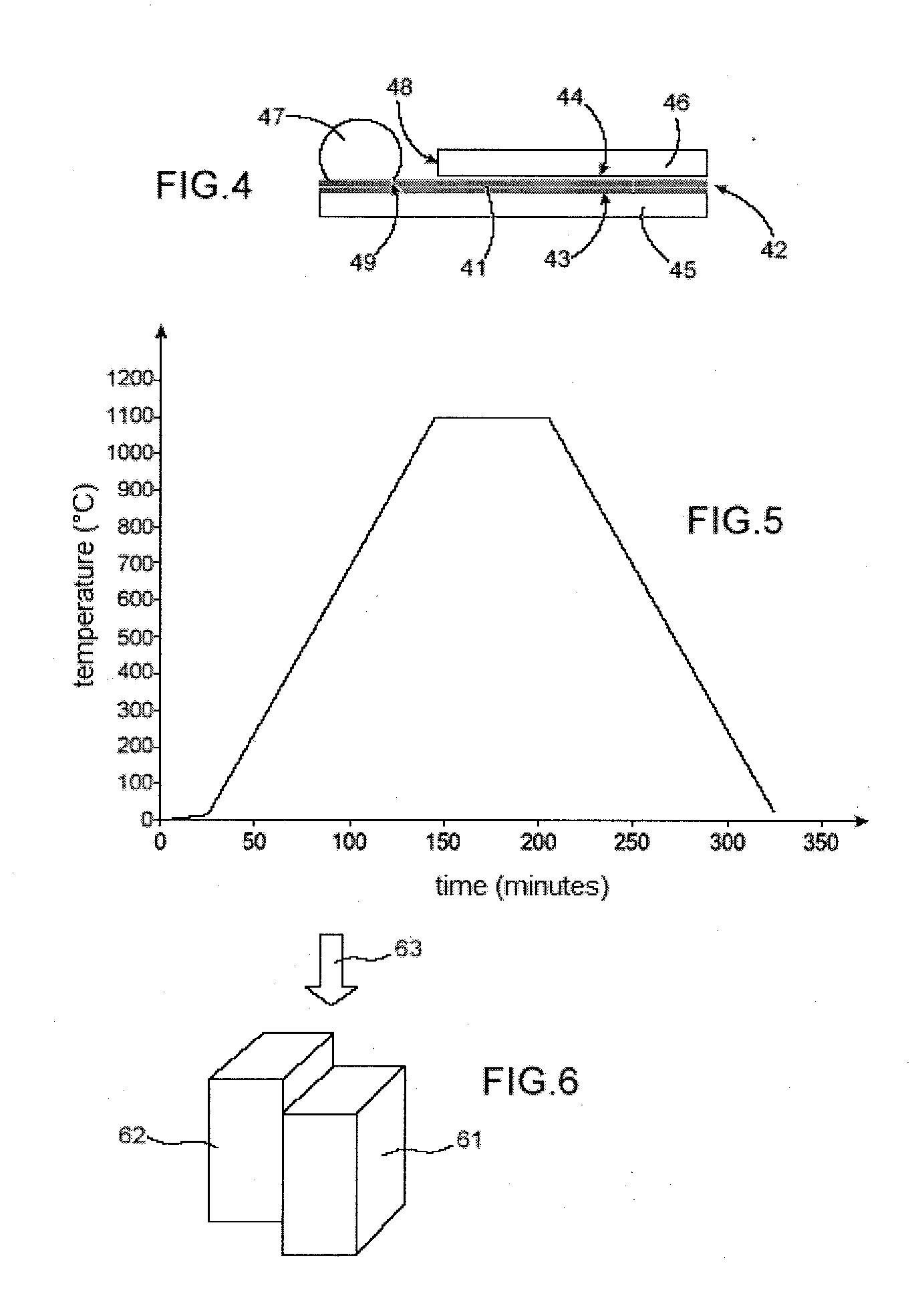
[0274]This example describes sessile drop tests performed with a brazing composition, braze alloy of the invention of composition 64% Si and 36% Ni (atomic percentage) i.e. 46% Si and 54% Ni in mass percentage, on sintered pure α-SiC observing a single brazing plateau at 1100° C.

[0275]a) Preparation of the Brazing Composition and Brazing Paste

[0276]The brazing composition concerned: 64 atomic % Si and 36 atomic % Ni was prepared from pieces of pure Si and pieces of pure Ni.

[0277]These pieces were weighed paying heed to the proportions of the brazing composition and placed in an alumina crucible. The assembly was placed in a metal furnace and subjected to a heat cycle with a plateau at 1250° C. under argon for 120 minutes.

[0278]After cooling, this gave an ingot. This ingot was crushed to obtain a powder.

[0279]An organic binder (NICROBRAZ® cement) was added to this mixture of powders to form a viscous paste.

[0280]b) Sessile Drop Test at 1100° C.

[0281]The brazing paste thus prepared wa...

example 2

[0289]This example describes sessile drop tests performed with a brazing composition, braze alloy of the invention having the composition 64% Si and 36% Ni in atomic percentages i.e. 46% Si and 54% Ni by mass, on a SiC / SiC Cerasep A40C® composite, observing a single brazing plateau at 1100° C.

[0290]a) Preparation of the Brazing Composition and Brazing Paste

[0291]The brazing composition concerned: 64 atomic % Si and 36 atomic % Ni was prepared as in Example 1.

[0292]A paste of brazing composition was formed as in Example 1.

[0293]b) Sessile Drop Test at 1100° C.

[0294]The brazing paste thus prepared was used to form a small mound of braze alloy of mass in the order of 50 mg. This mound of braze alloy was deposited on a plate of SiC / SiC composite with SiC matrix and SiC fibres. This composite is available from Snecma Propulsion Solide under the trade name CERASEP A40C®. This plate was previously cleaned before depositing the braze alloy.

[0295]The assembly of the mound of braze alloy and ...

example 3

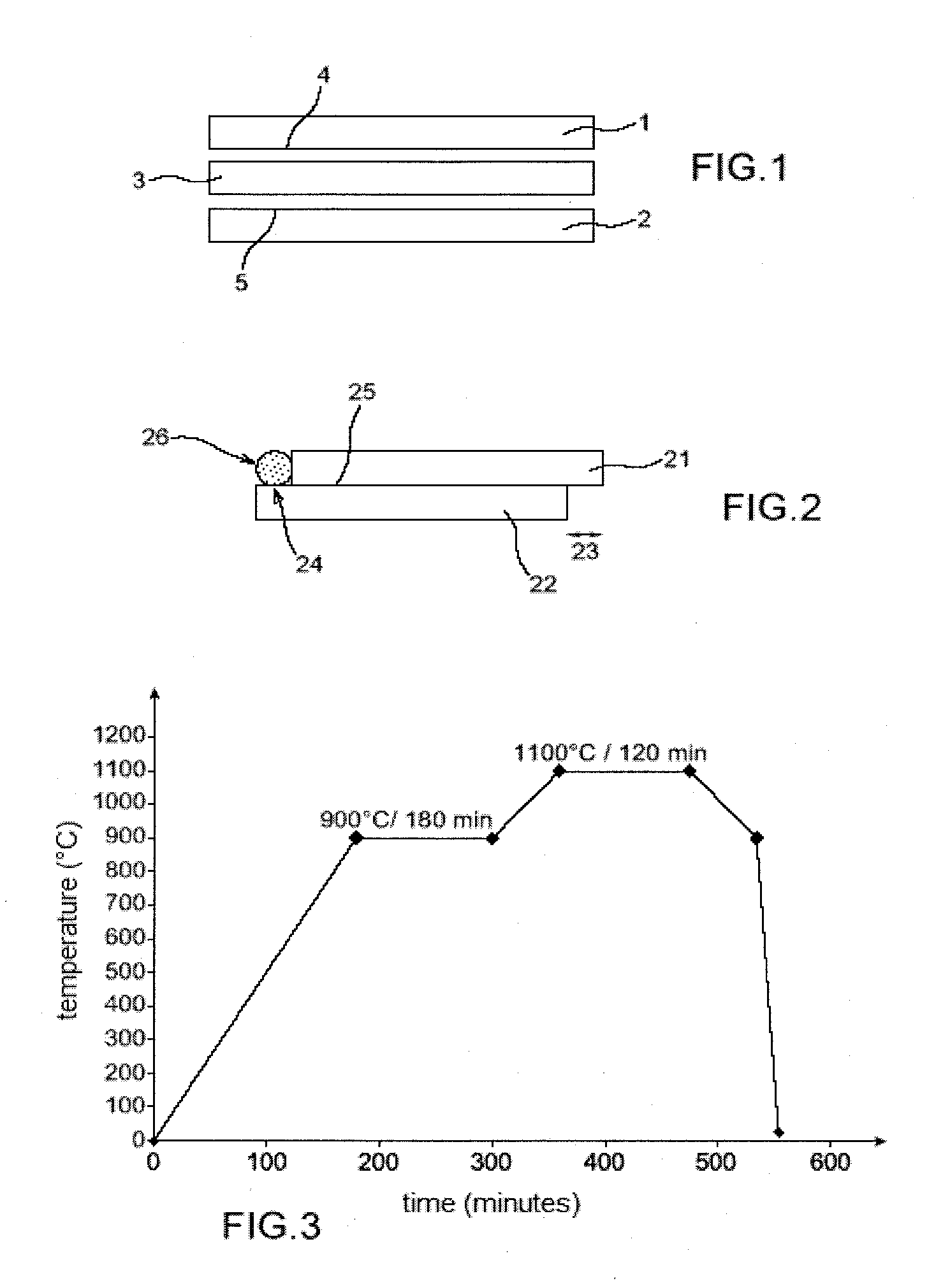
[0302]This example describes the preparation of bonds, joining between two parts made of sintered pure α-SiC silicon carbide using the brazing method according to the invention, the brazing being conducted in capillary configuration using a brazing composition, braze alloy of the invention composed of 64 atomic % Si and 36 atomic % Ni i.e. 46 mass % Si and 54 mass % Ni. This example also describes tests, mechanical testing performed on these assemblies.

[0303]a) Preparation of the Brazing Composition, of the Brazing Paste and of the Parts to be Assembled, Joined

[0304]The brazing composition concerned, namely 64 atomic % Si and 36 atomic % Ni was prepared in the manner described in Example 1.

[0305]A paste of brazing composition was prepared as in Example 1.

[0306]The parts made of sintered SiC to be assembled were plates of size 20×10 mm2 and thickness of 1.5 mm.

[0307]The parts were cleaned with acetone then ethanol and finally dried.

[0308]The substrates, parts were placed in contact l...


PUM

PropertyMeasurementUnit
Temperatureaaaaaaaaaa

Abstract

A method for joining, assembling, at least two parts comprising silicon carbide-based materials is provided. The parts are contacted with a non-reactive brazing composition, the assembly having the parts and the brazing composition is heated to a brazing temperature sufficient to melt the brazing composition, and the parts and the brazing composition are cooled so that, after solidification of the brazing composition, a moderately refractory joint is formed. The brazing composition is a binary alloy consisting, in atomic percentages, of 60% to 66% silicon and 34% to 40% nickel. Prior to contacting the parts with the brazing composition, a reinforcement is added. A composition comprising the brazing composition and a reinforcement is provided. A brazing paste, suspension comprising a powder of the brazing composition, a reinforcement, and an organic liquid cement, binder, or an organic viscous gel is provided. A joint and assembly obtained by the foregoing method is provided.

Description

TECHNICAL FIELD[0001]The present invention relates to a method for assembling, joining parts made of silicon carbide-based materials by non-reactive brazing with a non-reactive brazing composition and addition of a reinforcement, for the purpose in particular of preparing components entirely based on silicon carbide.[0002]The assembling, joining method according to the invention is generally implemented at a temperature not exceeding 1150° C., preferably between 1020° C. and 1150° C.[0003]The invention further relates to brazing compositions and to a joint and assembly obtained by this method, an assembly whose maximum temperature of use is generally between 850° C. and 880° C.[0004]In general by <<moderately refractory>> is meant a maximum temperature of use of the assembled component of generally between 850° C. and 880° C.[0005]By <<silicon carbide-based>> materials is generally meant a material whose SiC content is equal to or higher than 50% by weight, p...

Claims


Application Information

Patent Timeline
IPC IPC(8): B23K31/02B23K35/24
CPCB23K1/0008Y10T403/479B23K1/20B23K35/327B23K2201/14B23K2203/16C04B37/005C04B37/006C04B2235/3826C04B2235/422C04B2235/5244C04B2235/5248C04B2235/5256C04B2235/616C04B2235/656C04B2235/6562C04B2235/6565C04B2235/6567C04B2235/6581C04B2235/95C04B2235/96C04B2237/08C04B2237/083C04B2237/086C04B2237/16C04B2237/365C04B2237/38C04B2237/52C04B2237/597C04B2237/708C04B2237/82C04B2237/86B23K31/02B23K35/24B23K1/19B23K2103/172B23K2101/14B23K2103/16B23K1/00B23K35/30
Inventor CHAUMAT, VALERIEHENNE, JEAN-FRANCOIS
Owner COMMISSARIAT A LENERGIE ATOMIQUE ET AUX ENERGIES ALTERNATIVES
Learn More