
Control device for electric power steering apparatus

a control device and electric power steering technology, applied in the direction of steering initiation, instruments, vessel construction, etc., can solve the problems of insufficient torque and torque ripple for the control of the electric power steering apparatus, the fet is not an ideal switch, and the top and bottom arms are short, so as to achieve small torque ripple and high performance.

Active Publication Date: 2013-03-14
NSK LTD
View PDF9 Cites 17 Cited by
  • Summary
  • Abstract
  • Description
  • Claims
  • Application Information

AI Technical Summary

Benefits of technology

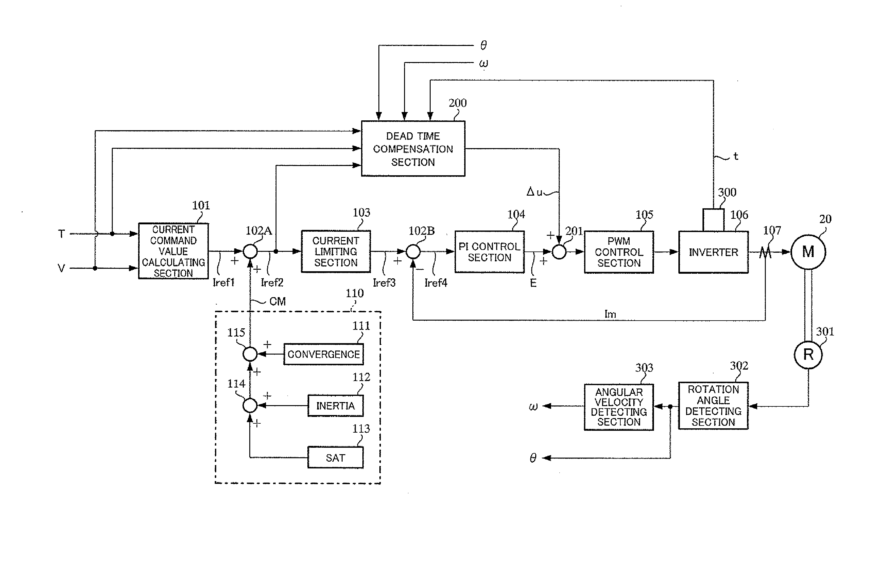
The control device for an electric power steering apparatus described in this patent uses a dead time compensation value that takes into account the temperature of the inverter. This results in a high performance control device that minimizes distortions in the motor voltage and current, and performs consistent dead time compensation regardless of temperature changes. Additionally, the compensation also takes into account changes in motor current that occur during steering, allowing for more accurate and efficient control.

Problems solved by technology

However, FET is not an ideal switch and requires a turn on time Ton and a turn off time Toff without instantly performing ON / OFF as instructed by gate signals.
As a result, for example, when an ON-instruction for FET1 and an OFF-instruction for FET4 are issued at the same time, FET1 and FET4 become ON at the same time and there is a problem that the top and bottom arms short.
However, existence of the above dead time becomes a cause that causes problems such as insufficient torque and torque ripple for control of the electric power steering apparatus.
Although the influence of the dead time Td with respect to the voltage distortion is described as above, even with respect to the current or the torque, there are undesirable influences caused by the dead time Td.
Further, the influence of the dead time Td with respect to the torque, appears in an insufficient output torque and an increase in torque ripple.
Moreover, since the actual current that is affected by the dead time Td, becomes smaller than the ideal current, the lack of output torque occurs.
In the dead time compensation, there is a problem that it is impossible to accurately detect the polarity sign(Im) of the current Im.
When measuring the polarity of the current Im, noises of the PWM control and the above-described zero clamping phenomenon of the current make it difficult to accurately measure the polarity of the current Im.
In particular, since it is a straight running state, for example, in running at a high speed, road vibration being transmitted to the steering wheel is small, thus unstable elements of the assist easily transmit as vibrations.

Method used


Image

  • Control device for electric power steering apparatus
  • Control device for electric power steering apparatus
  • Control device for electric power steering apparatus

Examples


first embodiment

[0060]Next, a configuration example (a first embodiment) of the dead time compensation section 200 will be described with reference to FIG. 9.

[0061]The current command value Iref2 from the addition section 102A, is inputted into a steering status determining section 210 and simultaneously inputted into a dead time characteristic section (a calculating section) 211. A dead time characteristic value Dt from the dead time characteristic section (the calculating section) 211, is inputted into a gain section 212. The dead time characteristic section (the calculating section) 211, outputs the dead time characteristic value Dt having a dead time characteristic of a characteristic shown in FIG. 10 with respect to the current command value Iref2. Further, a polarity determining section 213 is to determine the polarity of the input signal by characteristics with hysteresis, and the detected motor current Im, the current command value Iref2 or a model current based on the current command value...

second embodiment

[0076]Next, another configuration example (a second embodiment) of the dead time compensation section 200 will be described with reference to FIG. 14 corresponding to FIG. 9. With respect to the configurations that are the same as FIG. 9, the identical reference numerals are given without adding the explanations.

[0077]This embodiment is provided with a temperature correction subtraction value calculating section 220 that calculates a temperature correction subtraction value ts as the dead time temperature correction value in accordance with the temperature t from the temperature sensor 300 as the dead time temperature correction value calculating section, and simultaneously is provided with a subtraction section 221 that subtracts the temperature correction subtraction value ts from the dead time characteristic value Dtb with the polarity from the multiplication section 214 as the calculation processing section. The subtraction section 221 subtracts the temperature correction subtra...

third embodiment

[0078]Moreover, another configuration example (a third embodiment) of the dead time compensation section 200 will be described with reference to FIG. 17 corresponding to FIG. 9. With respect to the configurations that are the same as FIG. 9, the identical reference numerals are given without adding the explanations.

[0079]This embodiment is provided with a temperature correction gain calculating section 230 that calculates a temperature correction gain tg as the dead time compensation value in accordance with the temperature t from the temperature sensor 300 as the dead time compensation value calculating section, and simultaneously is provided with a multiplication section 231 that multiplies the dead time characteristic value Dtb with the polarity from the multiplication section 214 by the temperature correction gain tg as the calculation processing section. The multiplication section 231 multiplies the dead time characteristic value Dtb with the polarity by the temperature correct...


PUM


Abstract

A control apparatus for an electric power steering apparatus, including a dead time characteristic section that calculates a dead time characteristic value; a steering status determining section that determines a steering status; a gain section that varies a gain of the dead time characteristic value in accordance with a determination of the steering status; a polarity determining section that switches polarity determining methods in accordance with the determination of the steering status and determines a polarity on the basis of a detected current of a motor, a current command value or a model current; a temperature sensor that detects a temperature of an inverter; a dead time temperature correction value calculating section that calculates a dead time temperature correction value corresponding to the temperature; and a calculation processing section that calculates and processes the dead time temperature correction value with respect to a dead time compensation value with polarity based on an output of the gain section and outputs a dead time compensation value.

Description

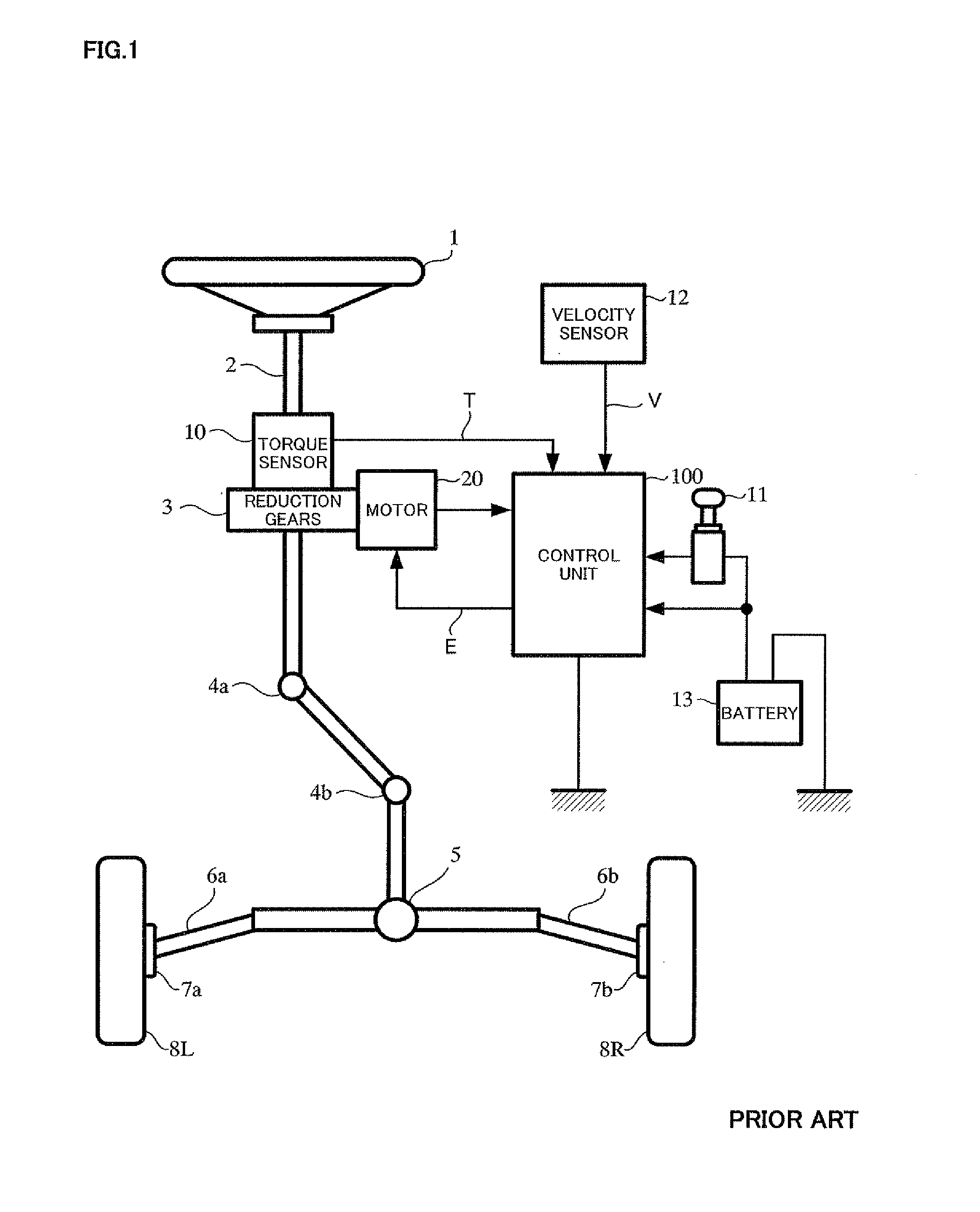
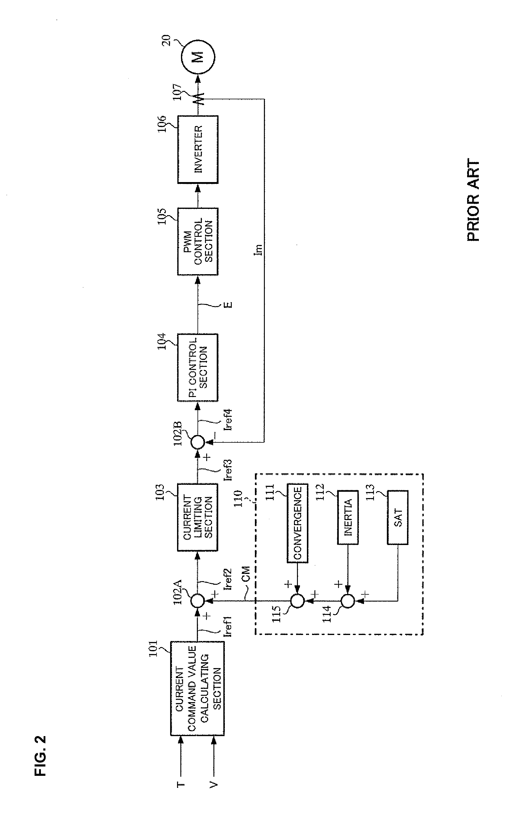
TECHNICAL FIELD[0001]The present invention relates to a control device for an electric power steering apparatus that provides a steering system of a vehicle with a steering assist force generated by a motor, and in particular to a control device for an electric power steering apparatus that improves dead time compensation of an inverter for a motor drive depending on a steering status and an inverter temperature.BACKGROUND ART[0002]An electric power steering apparatus that energizes a steering apparatus of a vehicle by using a rotational torque of a motor as an assist torque, applies a driving force of the motor as the assist torque to a steering shaft or a rack shaft by means of a transmission mechanism such as gears or a belt through a reduction mechanism. And then, in order to supply a current to the motor so that the motor generates a desired torque, an inverter is used in a motor drive circuit.[0003]A general configuration of a conventional electric power steering apparatus wil...

Claims


Application Information

Patent Timeline
Patent Type & Authority Applications(United States)
IPC IPC(8): B62D6/00B62D5/04
CPCB62D5/0463B62D6/00B62D5/0496B62D5/046
Inventor KITAZUME, TETSUYA
Owner NSK LTD
Learn More