Electromechanical transducer and method of manufacturing the electromechanical transducer
a technology of electromechanical transducers and transducers, applied in the field of electromechanical transducers, can solve the problems increase in bends, and achieve the effects of significant reduction of performance, variation in the conversion efficiency of elements, and variable membrane siz
- Summary
- Abstract
- Description
- Claims
- Application Information
AI Technical Summary
Benefits of technology
Problems solved by technology
Method used
Image
Examples
example 1
Transducer Including Structure
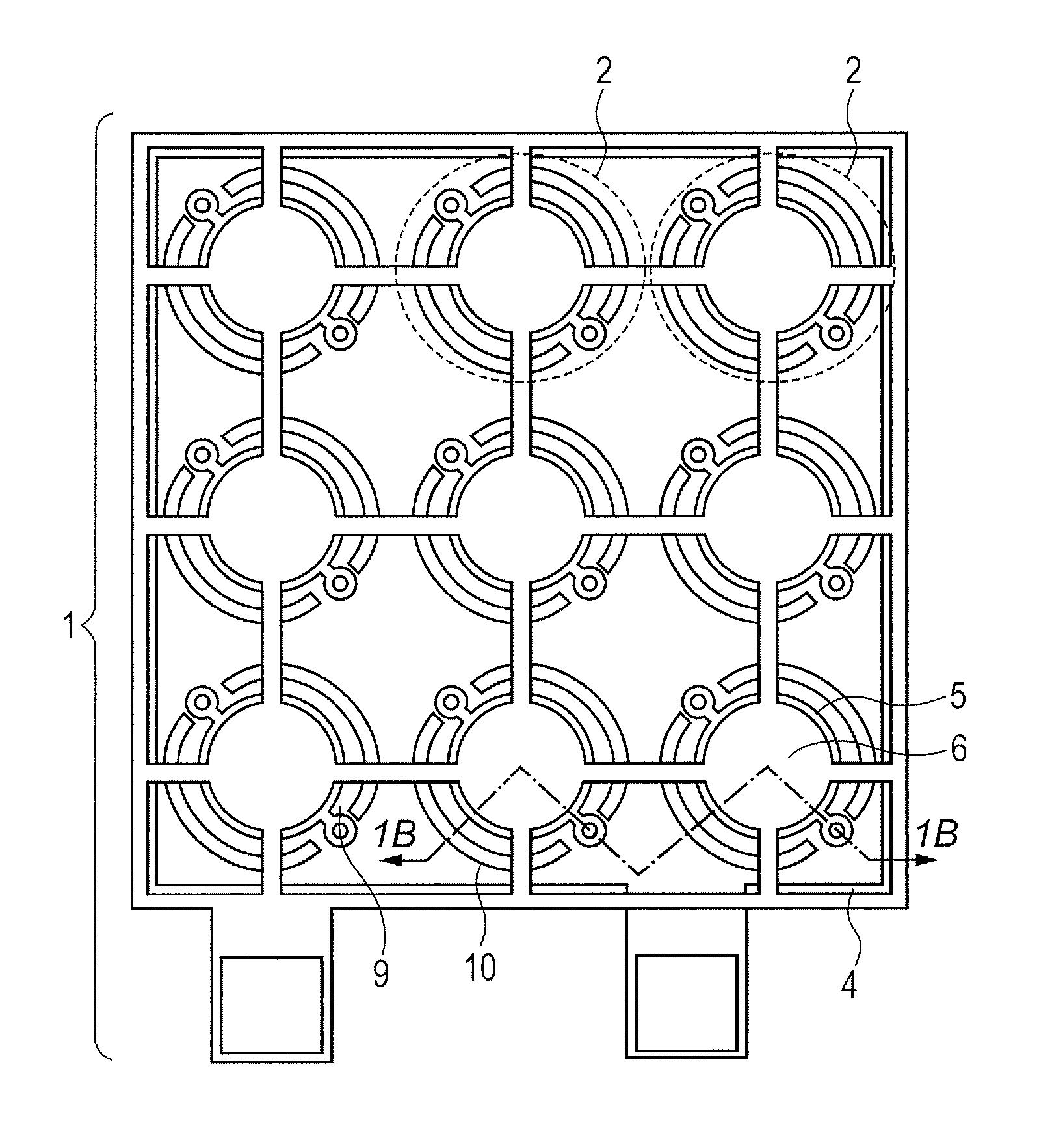
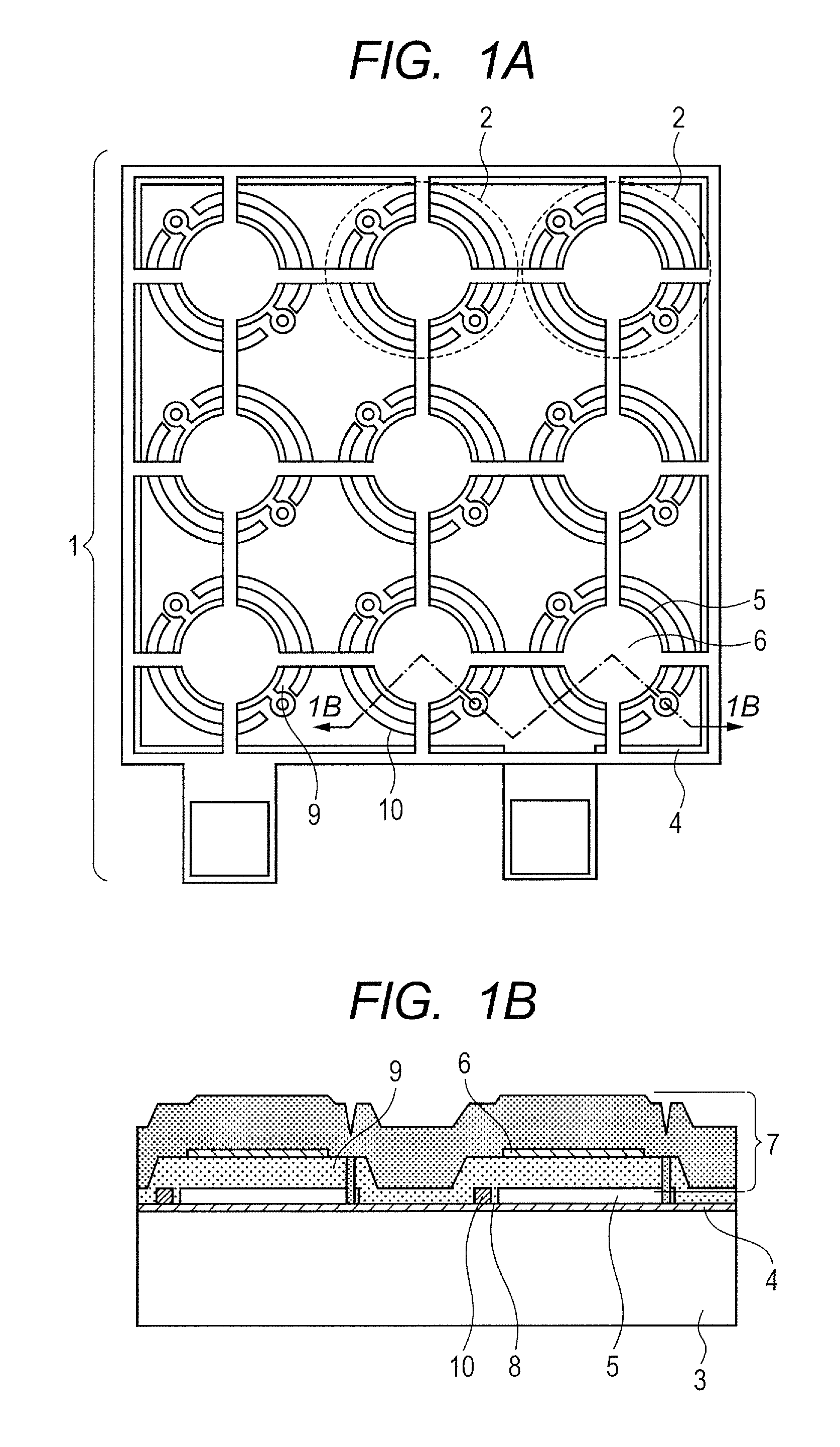
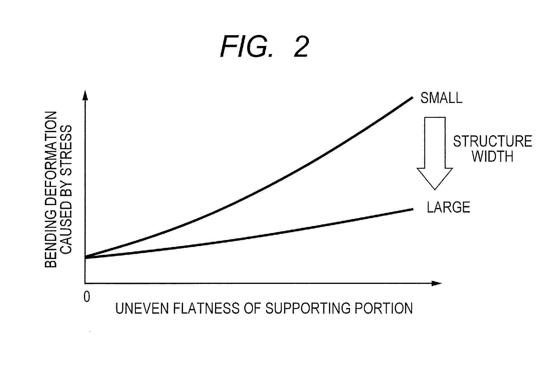
[0029]In FIG. 1B representing an ultrasound transducer as a first example of the present invention in the best manner, the height of the gap 5 formed by the sacrificial layer 33 (see, FIGS. 4C, 4D and 4E) is 100 to 300 nm. When the vibration film 7 or the gap 5 has a circular shape, the diameter thereof is 20 to 70 nm. In the example of FIG. 1B, although the vibration film 7 has a trilaminar structure including the second electrode 6, portions other than the second electrode 6 may be formed of silicon nitride, diamond, silicon carbide, oxide silicon, polysilicon, and so on. When the vibration film 7 is mainly formed of silicon nitride film formed by Plasma-enhanced-chemical-vapor-deposition (PECVD), the thickness of the vibration film 7 is approximately 500 nm to 2000 nm. The thickness of the second electrode 6 may be less than 20% of the entire vibration film 7. This is because the influence of a bend generated from the stress according to an electrode...
example 2
Transducer Array
[0033]An ultrasound transducer array as a second example of the present invention will be described. This example is a variation of the first example. In FIG. 3 representing this example, the length of one side of the entire size of an array 21 is 10 to 40 mm, and the ultrasound transducers (elements) 1 are one-dimensionally or two-dimensionally arranged therein. The internal constitution of the ultrasound transducer is equivalent to that in the example 1. Although there are wirings for inputting a drive signal from outside to each transducer or outputting a received signal, the wirings are changed according to an object of the ultrasound transducer array. In an example in FIG. 3, the ultrasound transducers 1 are arranged in a two-dimensional square lattice pattern. For example, when one side of the ultrasound transducer 1 is 1 mm and a square two-dimensional array with one side of 20 mm is used, the size is 20 mm×20 mm.
[0034]In the ultrasound transducer array 21 hav...
example 3
Manufacturing Method
[0036]A method of manufacturing an ultrasound transducer as a third example of the present invention will be described. In general, a capacitive micromachined ultrasonic transducer is manufactured by applying a semiconductor manufacturing process. In the manufacturing method in this example, in particular, a surface micromachining technology based on sacrificial layer etching is used. In FIGS. 4A, 4B, 4C, 4D, 4E, and 4F representing this example in the best manner, although the substrate 31 is preferably a single-crystal silicon substrate, the substrate 31 can be manufactured similarly, even though a glass substrate, an SC)I substrate, or the like is used.
[0037]A conductor is film-formed on the substrate 31 by vacuum deposition, a CVD method, or a film-formation method such as sputtering and plating, and the first electrode 32 is formed by photolithography and etching (FIG. 4A). The configuration of the first electrode 32 is required to have a low electrical resi...
PUM
| Property | Measurement | Unit |
|---|---|---|
| surface roughness | aaaaa | aaaaa |
| height | aaaaa | aaaaa |
| height | aaaaa | aaaaa |
Abstract
Description
Claims
Application Information
 - R&D
- Intellectual Property
- Life Sciences
- Materials
- Tech Scout
- Unparalleled Data Quality
- Higher Quality Content
- 60% Fewer Hallucinations
Browse by: Latest US Patents, China's latest patents, Technical Efficacy Thesaurus, Application Domain, Technology Topic, Popular Technical Reports.
© 2025 PatSnap. All rights reserved.Legal|Privacy policy|Modern Slavery Act Transparency Statement|Sitemap|About US| Contact US: help@patsnap.com


