Continuous or semi-continuous flow photobioreactor and method of use
- Summary
- Abstract
- Description
- Claims
- Application Information
AI Technical Summary
Benefits of technology
Problems solved by technology
Method used
Image

Examples
Embodiment Construction
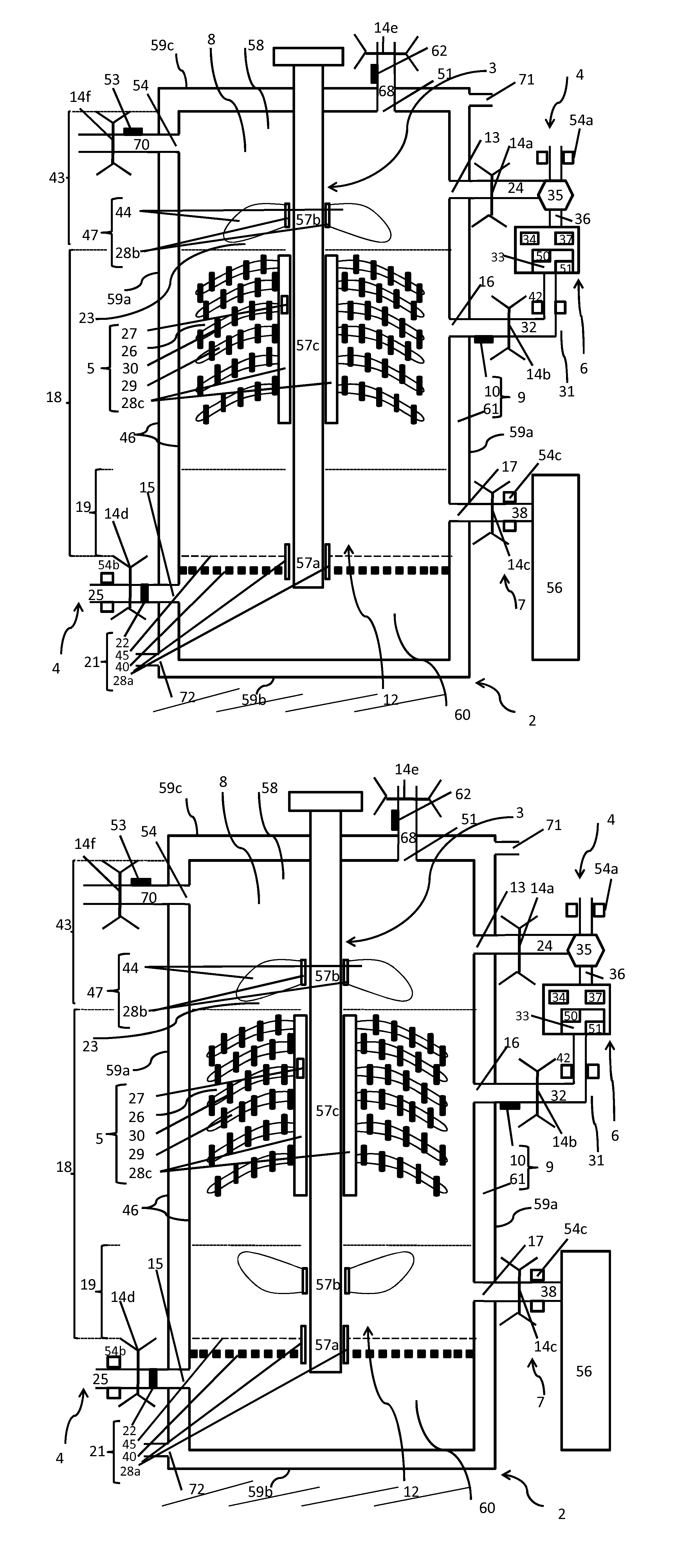
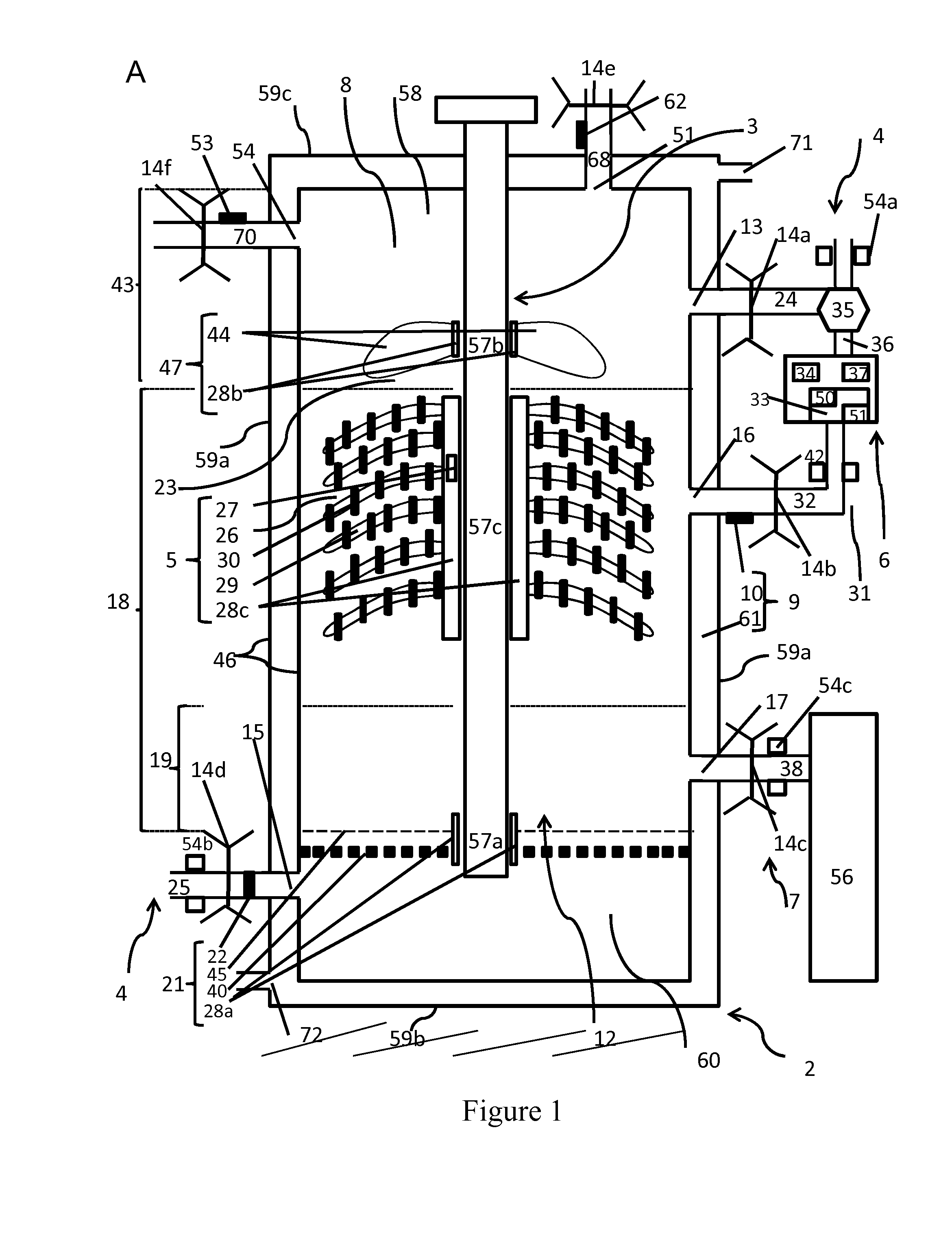
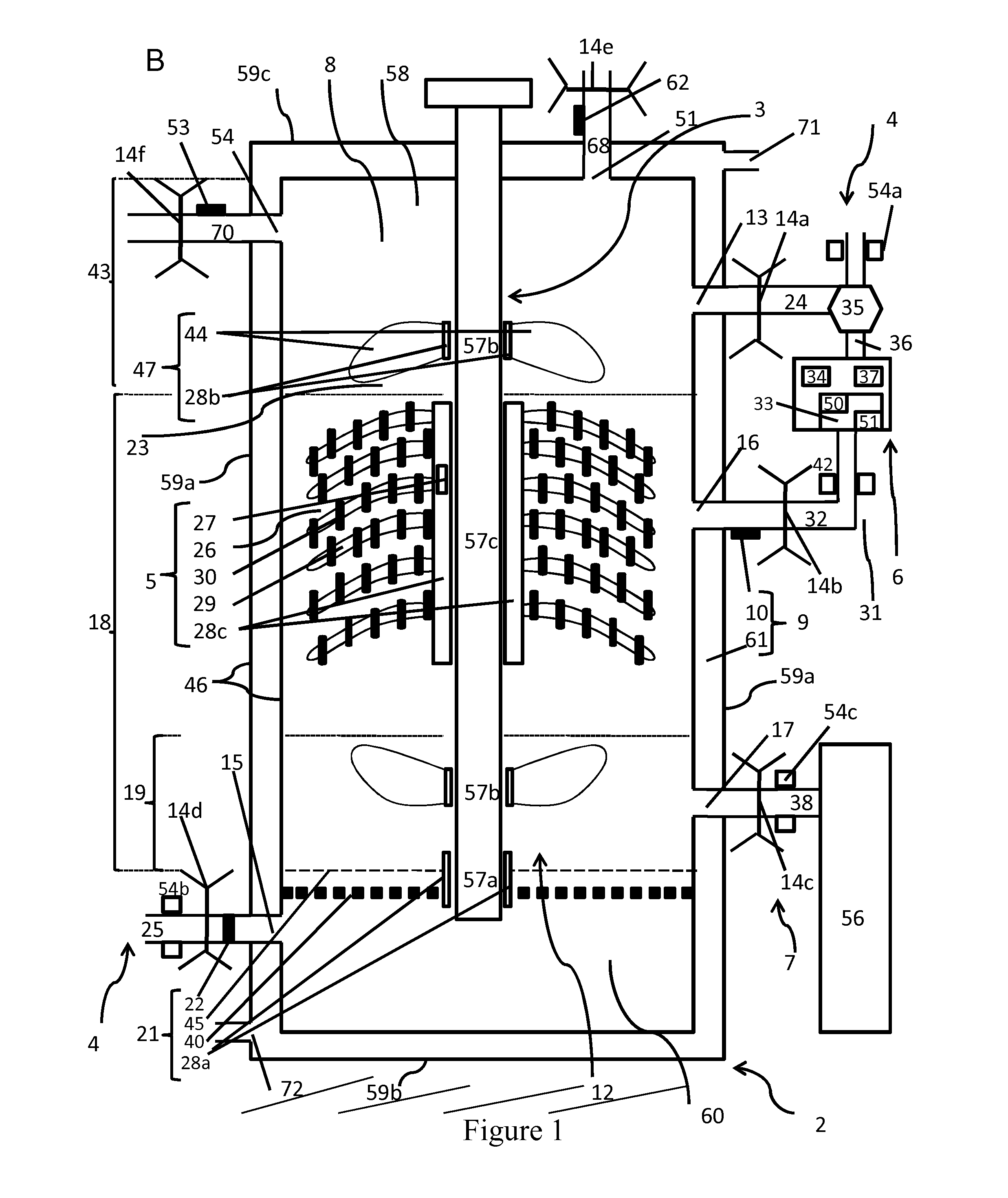
[0013]Disclosed herein is a photobioreactor for continuous or semi-continuous flow culturing photosynthesizing biomass, the photobioreactor including a housing defining an interior chamber comprising a culture chamber portion and a gas feeding chamber portion; a temperature regulation system; a flow-regulating system comprising a culture mixing and concentrating entity comprising a biomass-directing flow propulsion device; and a lighting system, the culture chamber portion comprising a culture concentrating zone and a culture harvesting zone, the temperature regulation system, the flow-regulating system being within the culture chamber portion, the lighting system being within the culture concentrating zone and the biomass-directing flow propulsion device system causing a vertical flow of culture medium contained in the housing such that the biomass is concentrated in the culture concentrating zone.
[0014]Advantageously, the biomass-directing flow propulsion device allows to concentr...
PUM
 Abstract
Description
Claims
Application Information
 - Generate Ideas
- Intellectual Property
- Life Sciences
- Materials
- Tech Scout
- Unparalleled Data Quality
- Higher Quality Content
- 60% Fewer Hallucinations
Browse by: Latest US Patents, China's latest patents, Technical Efficacy Thesaurus, Application Domain, Technology Topic, Popular Technical Reports.
© 2025 PatSnap. All rights reserved.Legal|Privacy policy|Modern Slavery Act Transparency Statement|Sitemap|About US| Contact US: help@patsnap.com