Composite material, electric contact electrode, electric contact film, conductive filler, electric contact structure using composite material, and manufacturing method of composite material

a technology of composite materials and manufacturing methods, applied in the field of composite materials, can solve the problems of micro sliding, electronic devices and the like may malfunction, and contact resistance may increase, and achieve the effect of long sliding li

Active Publication Date: 2013-04-04
DENSO CORP
View PDF5 Cites 6 Cited by
  • Summary
  • Abstract
  • Description
  • Claims
  • Application Information

AI Technical Summary

Benefits of technology

[0012]It is an object of the present disclosure to provide a composite material that can provide a long sliding life. Other objects of the present disclosure are to provide an electric contact electrode, an electric contact film, a conductive filler, and an electric contact structure using the composite material, and to provide a manufacturing method of a composite material, an electric contact electrode, an electric contact film, and a conductive filler.
[0014]Even when the oxide of the metal is generated on a surface of the composite material, the reducing agent reduces the oxide of the metal to the metal. Thus, the composite material can provide a long sliding life.

Problems solved by technology

Accordingly, a contact resistance may increase, and the electronic device and the like may malfunction.
However, under circumstances in which a micro sliding occurs for a long time, a gold plating film may be worn away due to the micro sliding.
Therefore, in order to secure a sufficient sliding life, it needs to increase a thickness of the gold plating film, and a cost increases.
Thus, an effect of restricting wear is not sufficient.

Method used


Image

  • Composite material, electric contact electrode, electric contact film, conductive filler, electric contact structure using composite material, and manufacturing method of composite material
  • Composite material, electric contact electrode, electric contact film, conductive filler, electric contact structure using composite material, and manufacturing method of composite material
  • Composite material, electric contact electrode, electric contact film, conductive filler, electric contact structure using composite material, and manufacturing method of composite material

Examples


Embodiment Construction

[0032]The inventor studied on a method that can increase a sliding life of an electric contact made of low-cost metal.

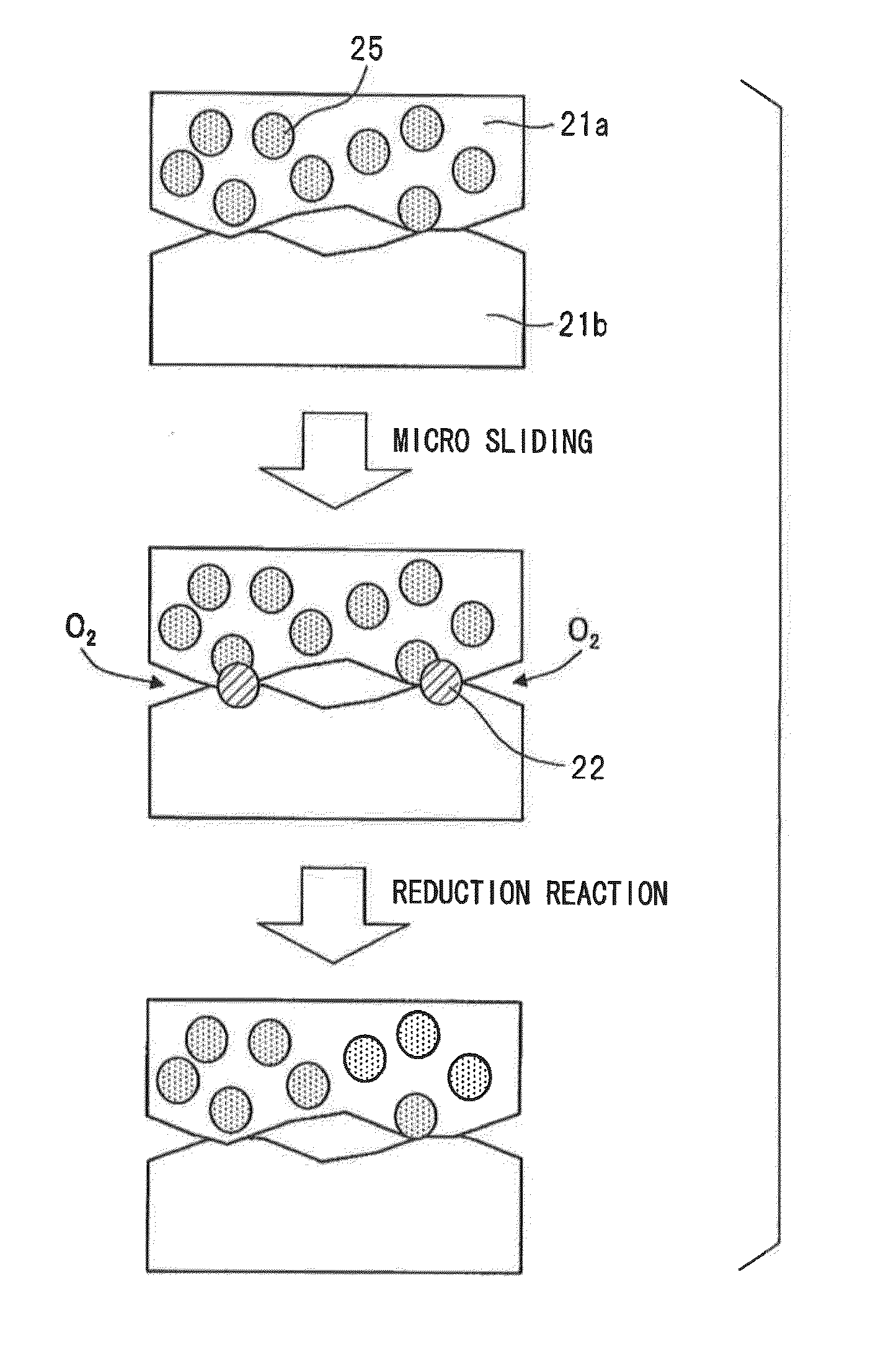
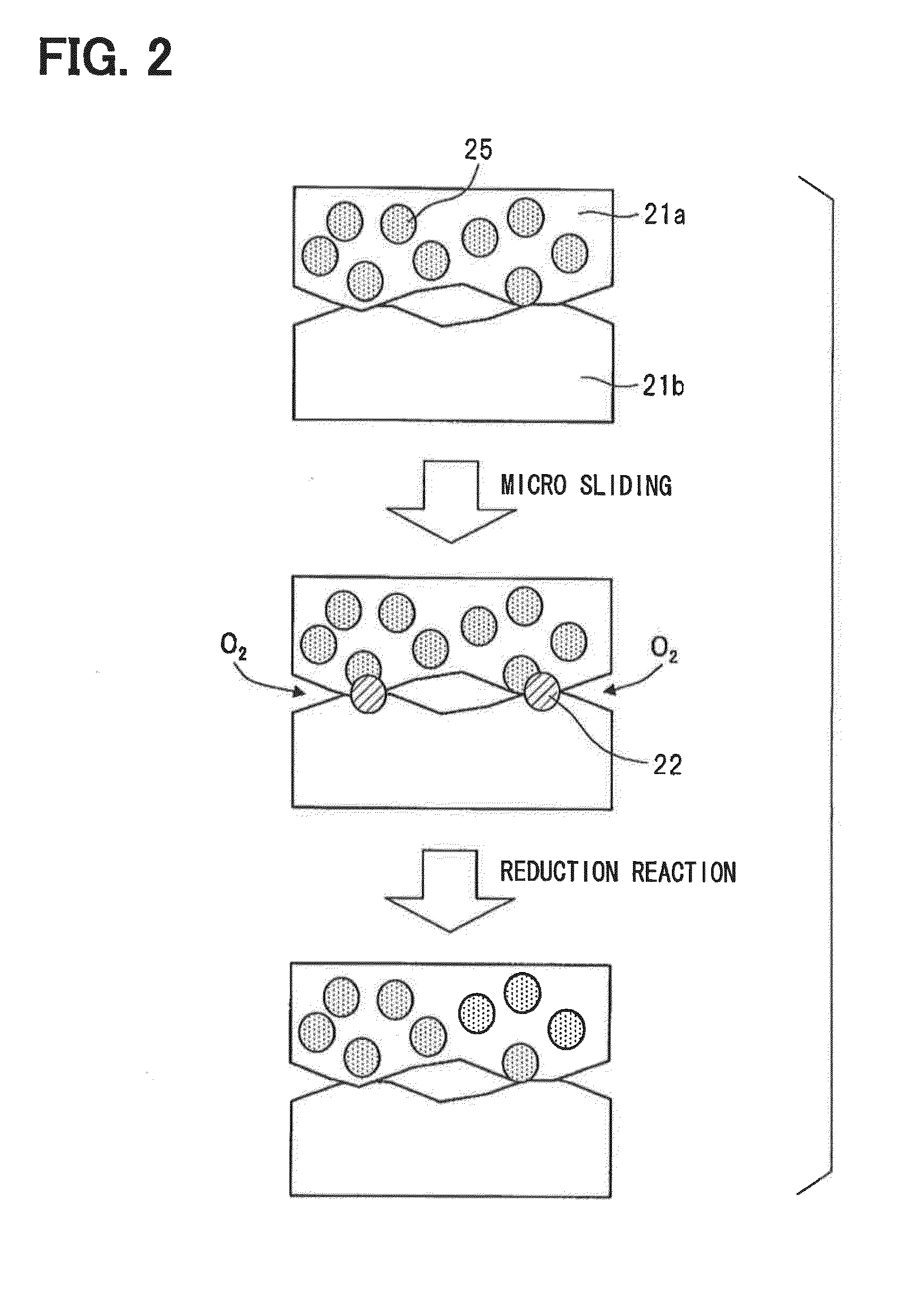
[0033]As a result of the study, the inventor found that when an electric contact is b formed by using a composite material in which a reducing agent that is capable of reducing an oxide of a metal at room temperature is dispersed in a metal matrix of the metal for an electric contact electrode, an electric contact film, or a conductive filler, even if the metal at a contact point is oxidized due to a repeated micro sliding, the reducing agent in the electrode, the film, or the conductive filler reduces the oxide of the metal to the metal.

[0034]The inventor also found that the composite material can be formed by adding the reducing agent and a complexing material as needed to a plating bath that includes a metal salt of the metal as primary component and performing electroplating so that eutectoid of the metal and the reducing agent is formed on a plated member.

[0035]...


PUM

PropertyMeasurementUnit
dispersion sizeaaaaaaaaaa
thicknessaaaaaaaaaa

Abstract

A composite material includes a metal matrix of a metal and a reducing agent. The reducing agent is dispersed in the metal matrix and is capable of reducing an oxide of the metal at room temperature. Even when the oxide of the metal is generated on a surface of the composite material, the reducing agent reduces the oxide of the metal to the metal

Description

CROSS REFERENCE TO RELATED APPLICATIONS[0001]The present application is based on and claims priority to Japanese Patent Application No. 2011-220318 filed on Oct. 4, 2011, the contents of which are incorporated in their entirety herein by reference.TECHNICAL FIELD[0002]The present disclosure relates to a composite material and a manufacturing method of a composite material. The present disclosure also relates to an electric contact electrode, an electric contact film, a conductive filler, and an electric contact structure using a composite material.BACKGROUND[0003]Conventionally, an electric contact, such as a connector, is made of copper or copper alloy electrode. The electrode is plated with nickel, and then an outermost surface of the electrode is plated with tin.[0004]When a temperature of usage environment changes, an electronic device and the like having an electric connection at an electric contact repeats expansion and contraction based on a thermal expansion coefficient of m...

Claims


Application Information

Patent Timeline
Patent Type & Authority Applications(United States)
IPC IPC(8): H01B1/02C25D1/00C25D3/38H01B5/00
CPCH01R13/03H01B1/026C25D3/32C25D15/00C25D3/58C25D3/60C25D3/38H01B1/02
Inventor MIYAKE, TOSHIHIRO
Owner DENSO CORP
Why Eureka
Try Eureka