Carbon Dioxide Separation Unit and Carbon Dioxide Separation Method

Inactive Publication Date: 2013-04-18
MITSUI ENG & SHIPBUILD CO LTD
View PDF2 Cites 4 Cited by
  • Summary
  • Abstract
  • Description
  • Claims
  • Application Information

AI Technical Summary

Benefits of technology

[0026]According to the present invention, when carbon dioxide contained in a gas to be treated is hydrated a

Problems solved by technology

However, the forming condition is generally high pressure and low temperature condition.
That is, carbon dioxide flows out of the reactor in a gaseous state (not contained in a liquid phase), and thus separation efficiency of c

Method used


Image

  • Carbon Dioxide Separation Unit and Carbon Dioxide Separation Method
  • Carbon Dioxide Separation Unit and Carbon Dioxide Separation Method
  • Carbon Dioxide Separation Unit and Carbon Dioxide Separation Method

Examples


Example

Example 1

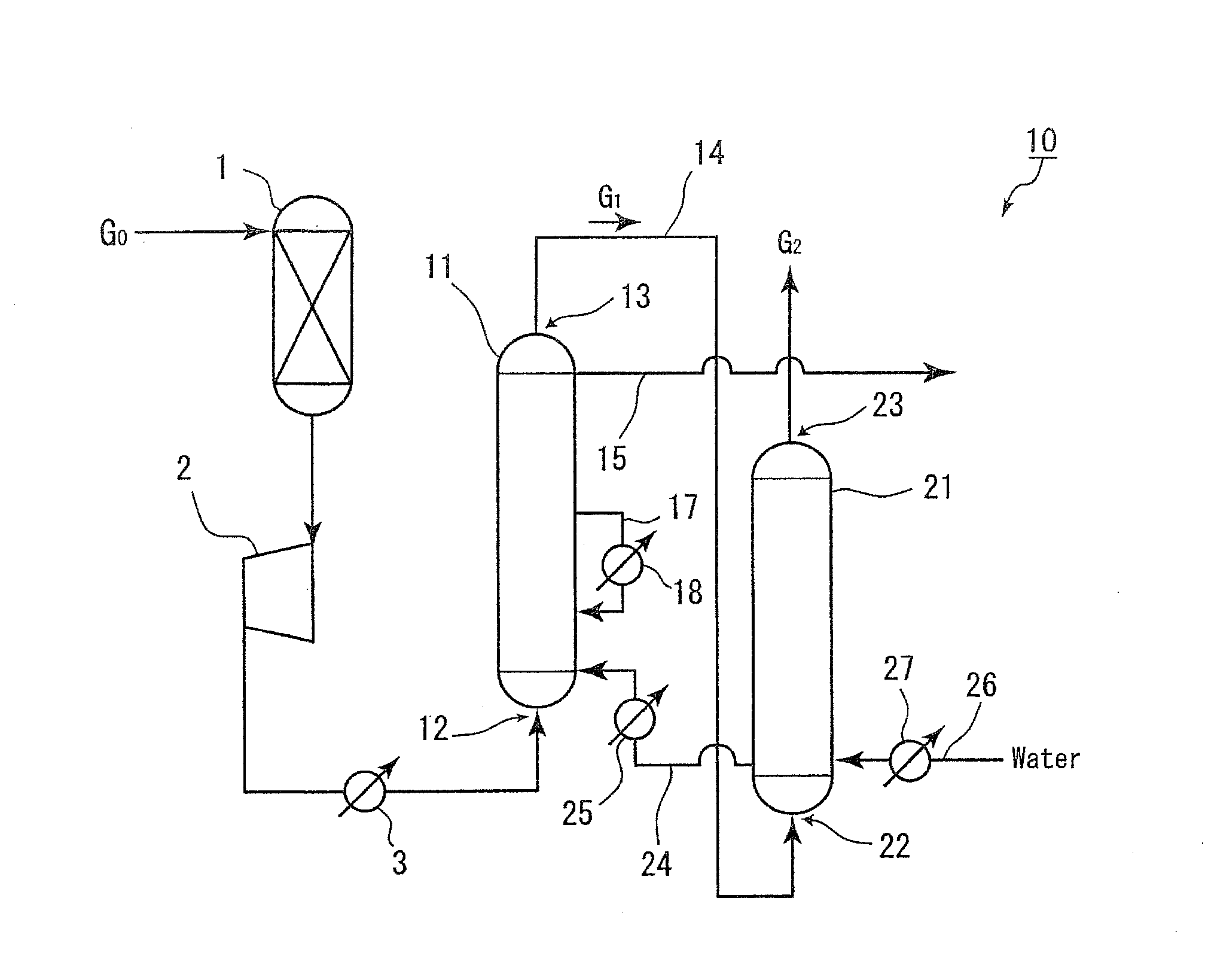
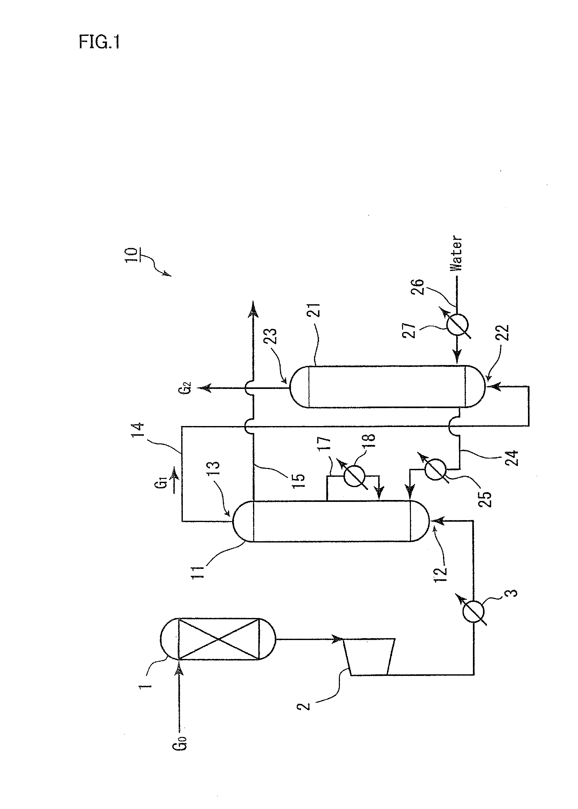
[0035]A carbon dioxide separator 10 related to the present example includes a carbon dioxide hydrate formation part 11 that forms carbon dioxide hydrate from a gas to be treated G0 containing carbon dioxide and water as a raw material. The gas to be treated G0 is, after conditioned to predetermined temperature and pressure (6 to 9 MPa and 1 to 2° C., for example) by a compressor 2 and a cooler 3, introduced from an inlet of a gas to be treated 12 disposed under the carbon dioxide hydrate formation part 11 into the inside of the carbon dioxide hydrate formation part 11. When the pressure of the gas to be treated G0 is high, the compressor 2 can be eliminated. Further, in order to remove moisture contained in the gas to be treated G0, a dehydrator 1 for the gas to be treated is preferably disposed prior to the carbon dioxide hydrate formation part 11.

[0036]The inside of the carbon dioxide hydrate formation part 11 is set to predetermined pressure and temperature where carbon ...

Example

Example 2

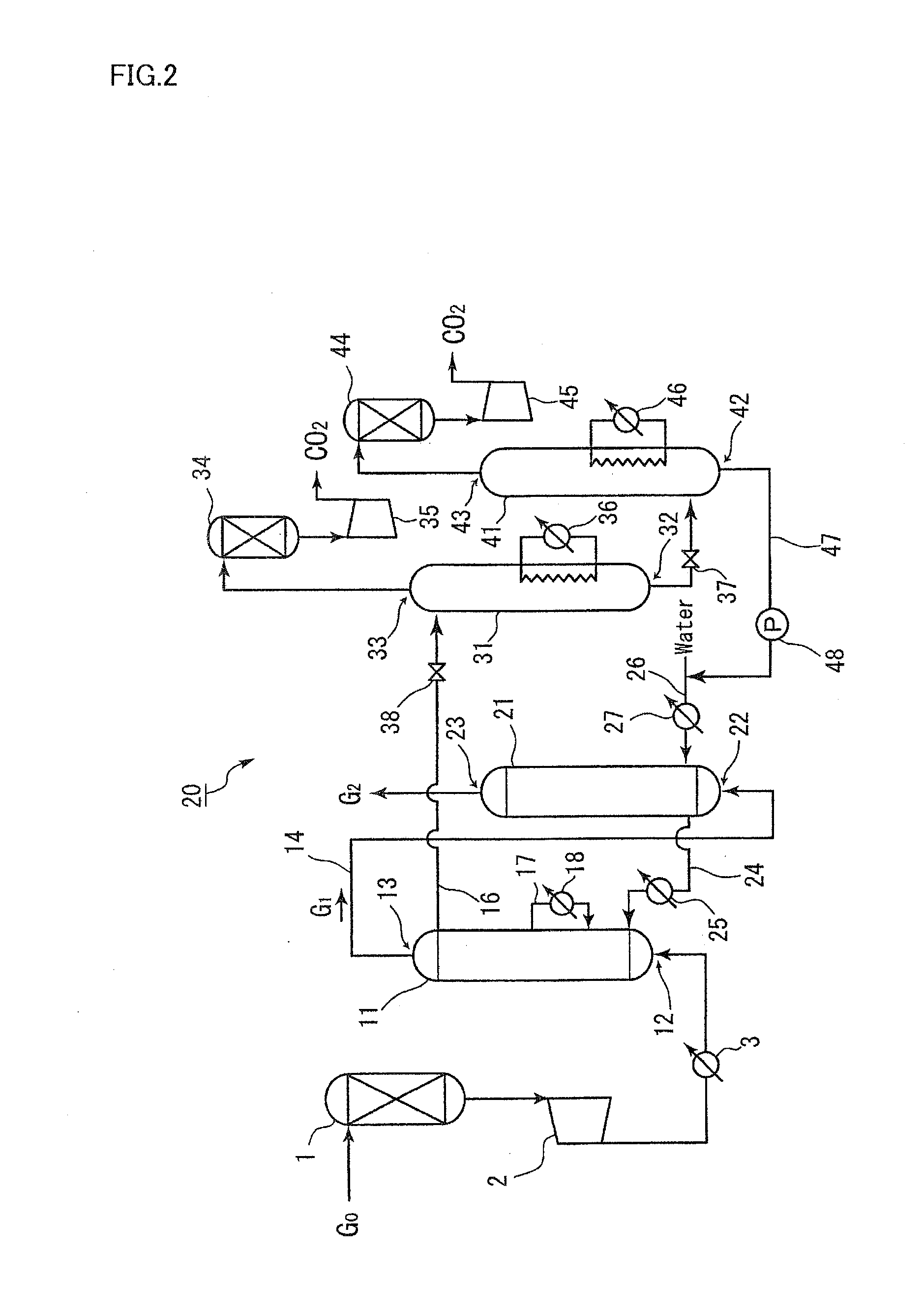
[0045]In the next place, another example of a carbon dioxide separator related to the present invention will be described. FIG. 2 is a schematic block diagram showing a carbon dioxide separator 20 related to example 2. Like characters represent like members as those of example 1, and description thereof will be omitted. A carbon dioxide separator 20 related to the present example includes, similarly to the example 1, a carbon dioxide hydrate formation part 11 and a carbon dioxide absorption part 21, further on a downstream side thereof, a gas hydrate decomposition part 31 and a carbon dioxide release part 41.

[0046]A slurry of carbon dioxide hydrate formed in the carbon dioxide hydrate formation part 11 is introduced via a line 16 into the gas hydrate decomposition part 31. In the gas hydrate decomposition part 31, a step of decomposing and re-gasifying carbon dioxide hydrate formed in the carbon dioxide hydrate formation part 11 is conducted. The re-gasification of carbon d...

Example

Example 3

[0053]Next, still another example of a carbon dioxide separator related to the present invention will be described. FIG. 3 is a schematic block diagram showing a carbon dioxide separator 30 related to example 3. Like characters represent like members as those of example 2, and description thereof will be omitted. A carbon dioxide separator 30 related to the present example includes, similarly to the example 2, a carbon dioxide hydrate formation part 11, a carbon dioxide absorption part 21, a gas hydrate decomposition part 31 and a carbon dioxide release part 41, further a dehydrator 51 between the carbon dioxide hydrate formation part 11 and the gas hydrate decomposition part 31.

[0054]In the carbon dioxide hydrate formation part 11, carbon dioxide in a gas to be treated G0 is hydrated to form a carbon dioxide hydrate slurry. In order to efficiently separate carbon dioxide in the gas to be treated G0, a water content of the carbon dioxide hydrate slurry is preferable to be 5...


PUM

PropertyMeasurementUnit
Pressureaaaaaaaaaa
Efficiencyaaaaaaaaaa

Abstract

The problem is to provide a carbon dioxide separator that, when hydrating carbon dioxide contained in a gas to be treated to separate, can separate carbon dioxide from the gas to be treated at high efficiency and a method therefor. For this, a carbon dioxide separator that includes: a carbon dioxide hydrate formation part where carbon dioxide hydrate is formed with a gas to be treated containing carbon dioxide and water as a raw material; and a carbon dioxide absorption part where high pressure gas that passed through the carbon dioxide hydrate formation part without being hydrated is brought into gas-liquid contact with water to let absorb carbon dioxide in the high pressure gas, in which water in the carbon dioxide absorption part is sent to the carbon dioxide hydrate formation part as the raw material water is provided.

Description

FIELD OF THE INVENTION[0001]The present invention relates to a separation unit of carbon dioxide contained in a gas to be treated such as a combustion exhaust gas or a process gas, and a method for separating carbon dioxide.BACKGROUND ART[0002]An integrated gasification combined cycle (IGCC) is gathering an attention as a power generation method where coal is gasified, and a gas turbine and a steam turbine are used in combination to generate electricity by efficiently converting coal into energy. In the IGCC, a process gas containing carbon dioxide (CO2) and hydrogen (H2) is formed, carbon dioxide is separated from the process gas, H2 gas is burned in the gas turbine to generate electricity, and, in the gas turbine, vapor produced when H2 gas is burned in the gas turbine is used to generate power at the steam turbine. A mixing ratio of carbon dioxide and hydrogen in the process gas is generally about 4:6.[0003]Examples of technologies that separate carbon dioxide contained in combus...

Claims


Application Information

Patent Timeline
IPC IPC(8): B01D53/14C01B32/50
CPCB01D53/1475B01D53/62B01D2252/103B01D2257/504B01D2258/0233C01B31/20B01D2258/0283Y02C10/04Y02C10/06B01D53/1425B01D2258/025C01B32/50Y02C20/40Y02P20/151
Inventor MIYAGAWA, MITSURUMATSUO, KAZUYOSHISAKURAI, SOUICHIROSAKAI, MASAKAZU
Owner MITSUI ENG & SHIPBUILD CO LTD
Why Eureka
Try Eureka