
Impact and erosion resistant thermal and environmental barrier coatings

a technology of thermal and environmental barrier coatings and anti-eroding, which is applied in the direction of superimposed coating processes, machines/engines, mechanical equipment, etc., can solve the problems of altering the effectiveness of the silica scale, sand erosion, and significant erosion damage from sand ingestion, so as to enhance the protection of impact and erosion, the effect of resisting impact and erosion damag

Inactive Publication Date: 2013-04-18
DIRECTED VAPOR TECH INT
View PDF10 Cites 24 Cited by
  • Summary
  • Abstract
  • Description
  • Claims
  • Application Information

AI Technical Summary

Benefits of technology

This patent describes a process for applying high temperature coatings to substrates that provide both environmental and thermal protection. The process involves the deposition of multiple layers using a vapor deposition technique, including a silicon-based bond coat, an EBC layer, and a TBC layer. These layers work together to enhance impact and erosion resistance, as well as limit damage from particle impacts during service. The patent also describes specific coating conditions and compositions that can further improve the toughness and performance of the coatings. Overall, the patent provides a technical solution for protecting substrates in high-temperature environments.

Problems solved by technology

This is especially the case when gas turbine engines are operated in sandy environments where erosion and impact damage from sand ingestion can be significant, especially on rotating parts.
In this case, sand erosion arises when particles entrained in the engine deviate away from gas streamlines due to inertial forces.
However, exposures of these materials to the high temperatures, pressures and velocities of water vapor containing combustion environments alter the effectiveness of the silica scale.
Such conditions result in the formation of hydrated silica species (Si(OH)x) and volatilization of the protective scale.
This results in decreased oxidation protection and rapid ceramic recession during service.
As a result, the environmental durability of these materials is not currently adequate for engine environments.
The success of prior EBC work has indicated the feasibility of incorporating ceramic components into current and future engine designs; however, several key coating challenges remain including higher temperature capability and prime reliance (in the presence of impact / erosion / corrosion conditions).
Perhaps the most critical issue is the prime reliant aspect of EBC performance, as this requirement fundamentally alters the design aspect of the high temperature coatings currently used on nickel-based superalloy substrates (i.e. thermal barrier coatings).
However, due the unreliability in the coating lifetime, the design life of the component is based on the uncoated component lifetime and no (or little) thermal protection benefit is taken to improve engine performance.
For the case of EBC coatings, the above design concept is not feasible.
At temperatures above 1100° C. in a combustion environment, the SiC—SiC components cannot tolerate even local spallation of the EBC layer without damage to the underlying component as the water vapor can locally attack the protective silica scale which thermally grows on the SiC surface.
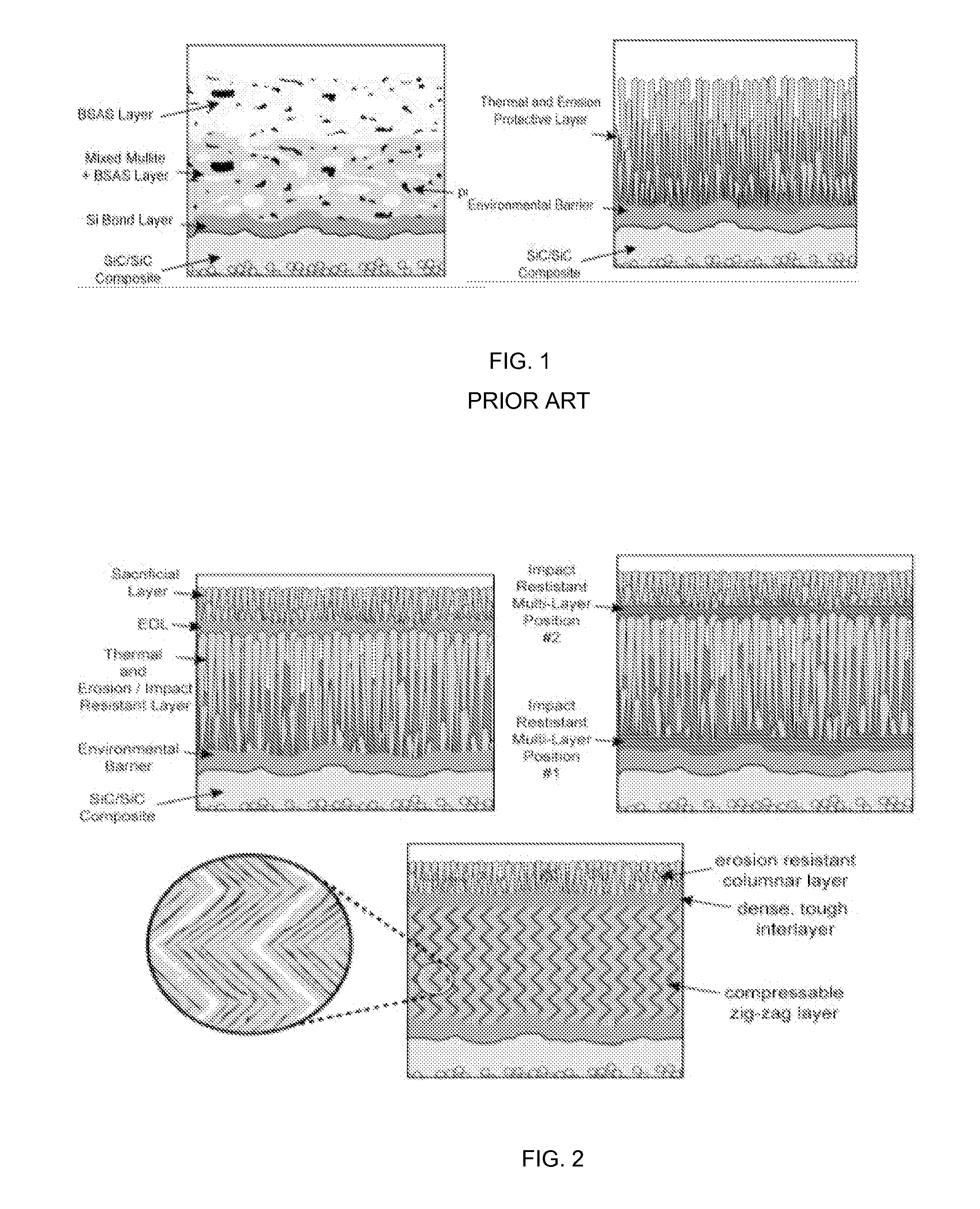
Despite their demonstrated success, current state-of-the-art EBC systems (silicon bond coat / mixed mullite+BSAS layer / BSAS top layer), have also been shown to be highly susceptible to foreign object damage (FOD) and erosion attack.
A lack of durability in these systems, however, has limited engine designers to use them only for component life extension.
This pore structure, however, has poorer in-plane compliance and thus, these coatings are generally less durable than EB-PVD coatings having a strain tolerant columnar microstructure.
The current life-limiting feature of TBCs is delamination of the ceramic topcoat.
As the TGO thickness exceeds several microns, it cracks laterally and the topcoat becomes detached, resulting in the failure of the TBC.
Impact and erosion damage of the top coat which can thin or locally remove sections of the coating can therefore exasperate coating failure mechanism and reduce coating lifetime.

Method used


Image

  • Impact and erosion resistant thermal and environmental barrier coatings
  • Impact and erosion resistant thermal and environmental barrier coatings
  • Impact and erosion resistant thermal and environmental barrier coatings

Examples


Embodiment Construction

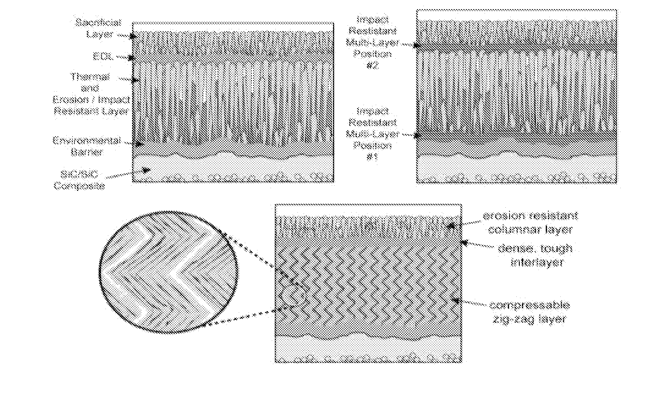
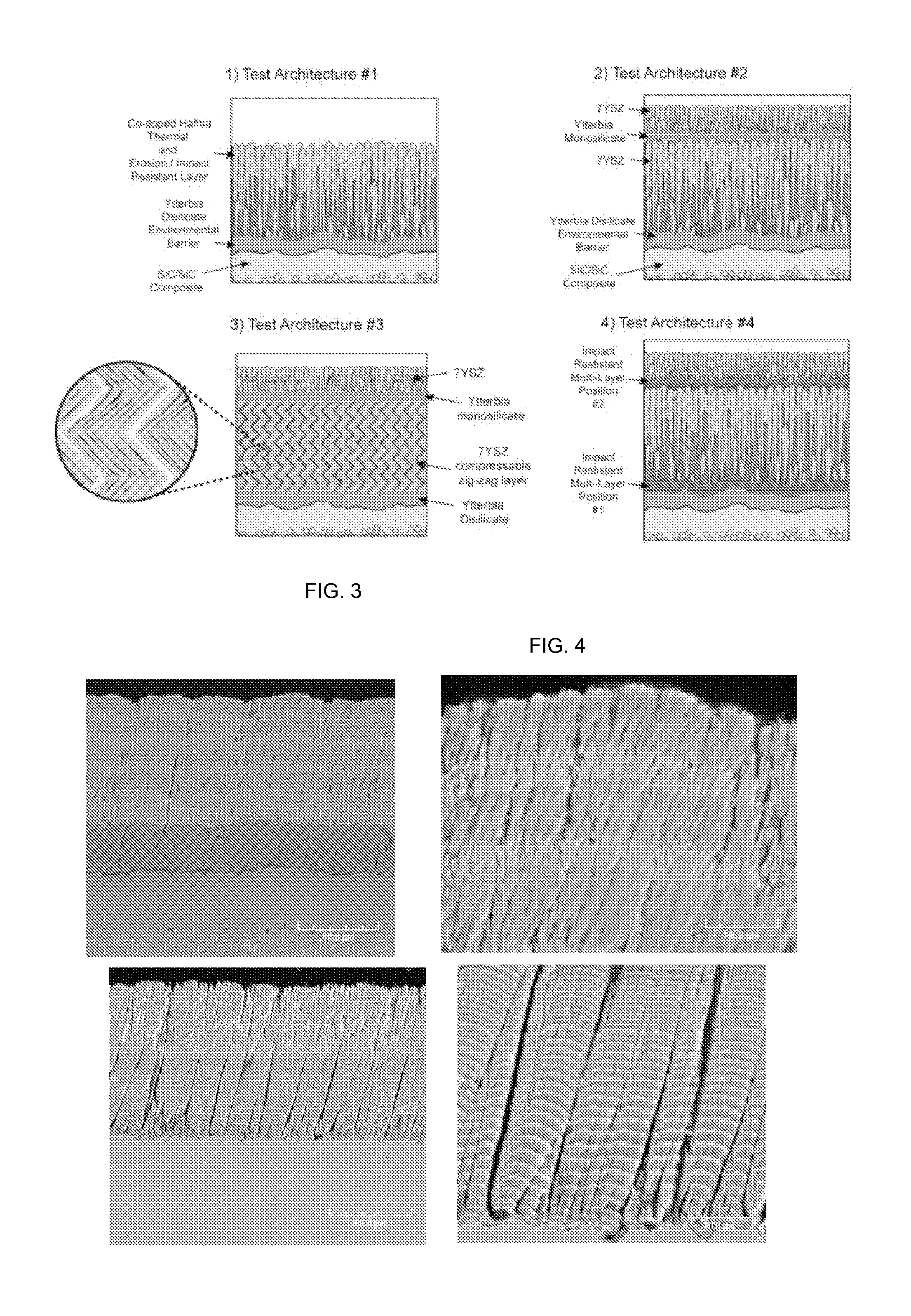
[0056]The use of Physical Vapor Deposition (PVD) and especially gas jet assisted PVD approaches enables the control over pore volume fraction and morphology in the deposited layer. Such approaches have been demonstrated to have the ability to form dense layers, layers with elongated columnar pores of a controllable spacing, layers having fine scaled feathery pores, nanoscaled globular pores and “zig-zag” shaped pores.

[0057]Fine scaled multi-layer coatings can be created which can uniquely alter the toughness and thermal conductivity of deposited layers.

[0058]Based on the above, it is clear that the use of PVD based processing approaches for T / EBC system deposition enables the ability to incorporate multiple novel concepts into an advanced impact resistant T / EBC system. The use of one or more of these concepts results in a T / EBC coating systems having improved toughness and the ability to absorb and / or deflect the energy imparted by the high velocity impact of a particle onto the coa...


PUM

PropertyMeasurementUnit
diameteraaaaaaaaaa
diameteraaaaaaaaaa
thicknessaaaaaaaaaa

Abstract

The present invention provides a process for the application of high temperature coating that provide enhanced impact resistance and erosion damage for the coatings. For high temperature coating systems that provide environmental protection to silicon based ceramics, the process provides the deposition of a silicon-based bond coat on the substrate using the directed vapor deposition with plasma activation and at least one supersonic gas jet nozzle. The process provides the deposition of an EBC layer using the directed vapor deposition with the gas jet nozzle. In one embodiment, the thermal barrier layer may also contain one or more dense embedded layers which further promote impact resistance. Within the process, the particular layers, silicon bond coat, EBC layer and / or TBC layer may be deposited together or specific novel layers applied in combination with other layers deposited using prior known deposition techniques.

Description

RELATED APPLICATION[0001]The present application relates to and claims priority to Provisional Patent Application Ser. No. 61 / 548,006 entitled “IMPACT AND EROSION RESISTANT THERMAL AND ENVIRONMENTAL BARRIER COATINGS” having a priority date of Oct. 17, 2011.GOVERNMENT SUPPORT[0002]Work described herein was supported by the U.S. Navy under contract N6833510C0231, Phase I SBIR and the Army under contract W911QX-08-C-0040. The United States government has certain rights in the invention.COPYRIGHT NOTICE[0003]A portion of the disclosure of this patent document contains material, which is subject to copyright protection. The copyright owner has no objection to the facsimile reproduction by anyone of the patent document or the patent disclosure, as it appears in the Patent and Trademark Office patent files or records, but otherwise reserves all copyright rights whatsoever.FIELD OF THE INVENTION[0004]The present invention relates generally to the field of designing and applying protective c...

Claims


Application Information

Patent Timeline
Patent Type & Authority Applications(United States)
IPC IPC(8): C23C16/50C23C16/48
CPCC23C14/0635C23C14/083C23C14/228C23C14/30C23C28/42C23C28/321C23C28/322C23C28/3455C23C28/042C04B41/89F01D5/288C04B41/009C04B41/52F01D25/007F05D2230/312F05D2300/175F05D2300/211C04B35/565C04B35/80C04B41/0054C04B41/0072C04B41/4529C04B41/5096C04B41/5024C04B2103/0021C04B41/5042Y02T50/60
Inventor HASS, DEREKGOGIA, BALVINDER
Owner DIRECTED VAPOR TECH INT
Learn More