Method for producing nitride crystal and nitride crystal

a technology of nitride crystal and nitride crystal, which is applied in the direction of semiconductor lasers, bulk chemical production, transportation and packaging, etc., can solve the problems of poor material use efficiency, difficult to produce nitride crystal at a high growth rate, so as to reduce time and effort, increase the production efficiency of nitride crystal, and ensure the effect of oxygen doping

Active Publication Date: 2013-05-02
MITSUBISHI CHEM CORP
View PDF1 Cites 20 Cited by
  • Summary
  • Abstract
  • Description
  • Claims
  • Application Information

AI Technical Summary

Benefits of technology

[0019]In consideration of those heretofore-existing problems, the present inventors have further made assiduous investigations for the purpose of efficiently producing a nitride crystal of good quality by controlling the condition of the crystal starting material for use in producing a nitride crystal according to an ammonothermal process to thereby increase the crystal growth rate and to increase the starting material use efficiency.
[0031]According to the third invention, a nitride crystal is produced by the use of a nitride crystal starting material having an angle of repose falling within a specific range. Therefore in the invention, the solvent convection flow in crystal growth is hardly retarded, the dissolution rate of the starting material can be increased and the crystal growth rate can be increased, and a nitride crystal can be produced efficiently. Consequently, according to the third invention, the growth time can be shortened, the nitride crystal starting material can be efficiently formed into a nitride crystal and the production cost can be noticeably reduced. The nitride crystal produced according to the third invention can be effectively used as a high-quality crystal in devices.

Problems solved by technology

The present inventors investigated production of a nitride crystal by the use of the nitride crystal starting material obtained according to the method described in Patent Reference 1, but have known that it is not easy to produce the nitride crystal at a high growth rate.
In addition, as described in Patent Reference 2, the inventors investigated production of a nitride crystal by charging the starting material so as to fill up the gap between the nitride crystal starting materials, but have known that it is not easy to produce the nitride crystal at a high growth rate and that the material use efficiency is poor.
Further, the inventors tried production of a polycrystalline nitride merely by using, as a nitride crystal starting material, the nitride crystal produced according to the method described in Patent Reference 3 and Patent Reference 4, but have known that it is difficult to produce the nitride crystal at a desired growth rate.
For the ammonothermal process, only the condition for basic crystal growth is investigated, and any method for obtaining a high-quality crystal having a desired electroconductivity is not as yet established.
However, the activation ratio in the case where oxygen is used as the n-type dopant in the nitride crystal produced according to an ammonothermal process has not been clarified.
In addition, in an ammonothermal process, used are dopants that are derived from various types of dopant sources, and therefore, it has been impossible to establish the oxygen doping condition for obtaining a nitride crystal having a desired carrier concentration.
Accordingly, there has been a problem that it is difficult to obtain a nitride crystal having a desired carrier concentration.
Further, in the ammonothermal process, the oxygen doping condition has not been established for obtaining a nitride crystal having a desired carrier concentration, and consequently, it is impossible to attain accurate oxygen doping therefore providing another problem in that a high-quality nitride crystal could not be obtained.
Moreover, in order to obtain a nitride crystal having an intended carrier concentration according to the ammonothermal process, various conditions must be tried and investigated, therefore providing still another problem in that the production efficiency could not increase.

Method used


Image

  • Method for producing nitride crystal and nitride crystal
  • Method for producing nitride crystal and nitride crystal
  • Method for producing nitride crystal and nitride crystal

Examples


preparation example 1

Preparation of Nitride Crystal Starting Material for Use in Example 1, Example 2 and Example 6

[0274]The angle of repose and the bulk density of the GaN polycrystalline particles, which is used as the starting material in the production method for a nitride crystal in Example 1, Example 2 and Example 6, were controlled according to the method mentioned below.

[0275]Coral-like GaN polycrystalline particles (of which the maximum diameter of the tertiary particle is from 0.5 to 50 mm), as produced according to a hydride vapor phase epitaxial (HVPE) method but not using a seed crystal, were made to collide with each other and were thus ground so that the maximum diameter of the tertiary particles thereof could be from 0.5 mm to 20 mm, whereby the angle of repose and the bulk density of the particles were controlled. In this, the particles were ground according to a method where the GaN polycrystalline particles were made to collide with each other in the atmosphere at a relative humidity ...

example 1

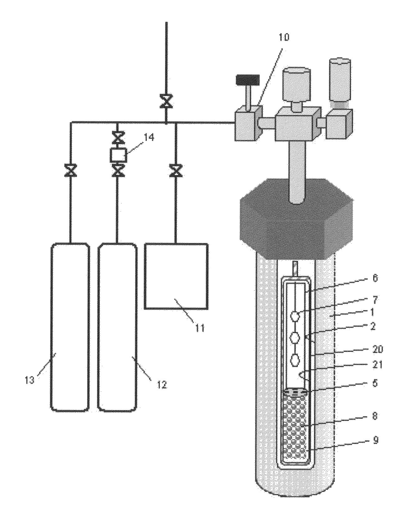
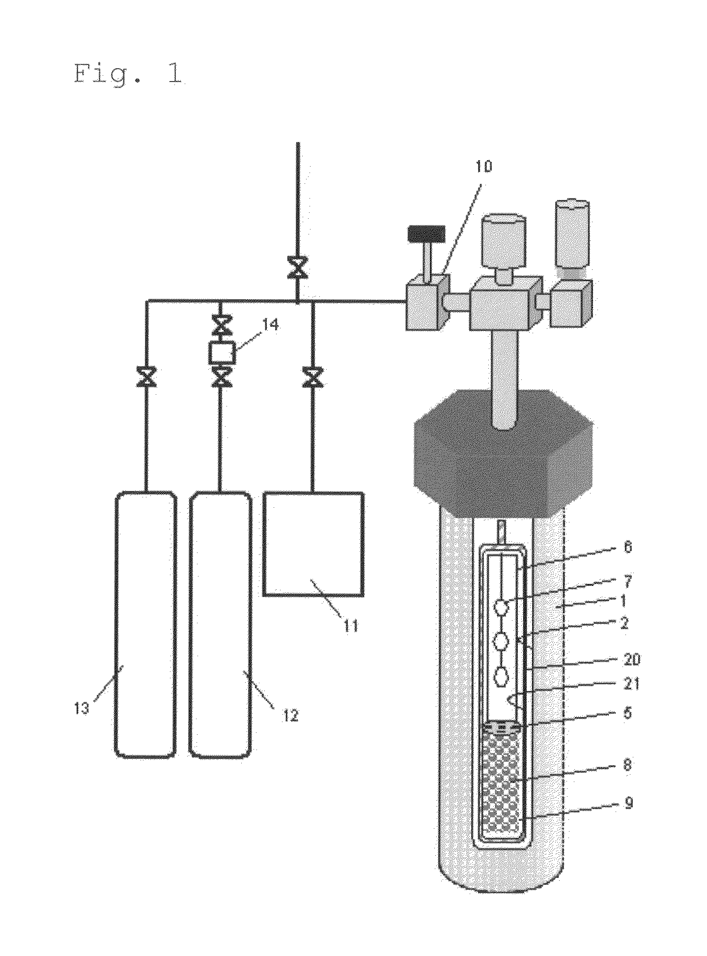
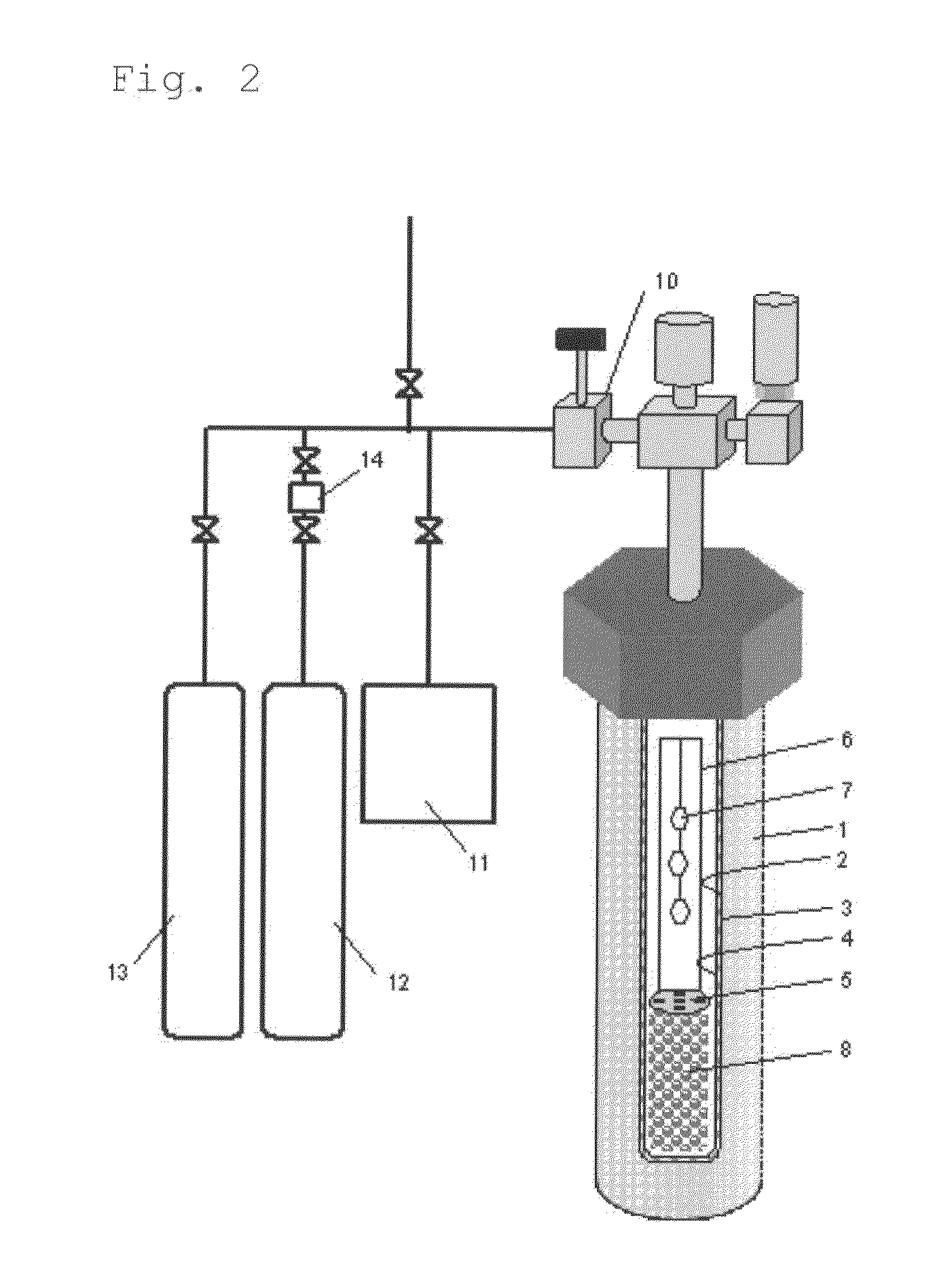
[0285]A RENE 41-made autoclave 1 (inner volume, about 345 cm3) was used as a pressure vessel, in which a Pt—Ir-made capsule 20 was used as a reactor for crystal growth. The inner diameter of the Pt—Ir-made capsule was 2.5 cm. The capsule was filled in a fully-dried nitrogen atmosphere globe box. As the starting material 8, 130.36 g of GaN polycrystal obtained in preparation example 1 was metered and set in the lower region of the capsule (starting material charging region 9) along with a Pt-made net-like structure (not shown, 30.4 g, volume 1.39 cm3) to support the baffle plate and the seed crystal supporting frame therein. In this, the height from the lowermost edge (capsule lower part) of the region with the GaN polycrystal therein and the uppermost edge thereof was about 15 cm. About ⅔ of the Pt structure was kept buried in the region where the GaN polycrystalline starting material was kept therein. From the above, the bulk density of the GaN polycrystal in the starting material ...

example 2

[0293]In Example 2, NH4I having a purity of 99.999% and GaF3 having a purity of 99.999% were used in place of HCl as acidic mineralizing agents, and the mineralizing agents were so metered and put into the capsule that the total of the I concentration and the F concentration could be 2.25 mol % relative to the charged NH3 amount, and the temperature and the pressure for crystal growth were changed to those shown in Table 1. The bulk density of the starting material and the others in the process were the same as in Example 1, and with that, a gallium nitride crystal was precipitated on the seed crystal in condition of Table 1.

[0294]The weight of non-dissolution starting material after the growth step was checked, and was 82.19 g. The dissolution rate of the GaN polycrystalline starting material was calculated and shown in the Table 1. The recovered GaN polycrystalline starting material was analyzed and was confirmed to have been wholly dissolved to be small particles. From this, it i...


PUM

PropertyMeasurementUnit
densityaaaaaaaaaa
diameteraaaaaaaaaa
diameteraaaaaaaaaa

Abstract

A high-quality nitride crystal can be produced efficiently by charging a nitride crystal starting material that contains tertiary particles having a maximum diameter of from 1 to 120 mm and formed through aggregation of secondary particles having a maximum diameter of from 100 to 1000 μm, in the starting material charging region of a reactor, followed by crystal growth in the presence of a solvent in a supercritical state and / or a subcritical state in the reactor, wherein the nitride crystal starting material is charged in the starting material charging region in a bulk density of from 0.7 to 4.5 g / cm3 for the intended crystal growth.

Description

CROSS-REFERENCE TO RELATED APPLICATIONS[0001]The present application claims the benefit of priority under 35 U.S.C. 119 from U.S. Provisional Patent Application No. 61 / 552,801 filed Oct. 28, 2011, Japanese Patent Application No. 25711 / 2012 filed Feb. 9, 2012 and Japanese Patent Application No. 188099 / 2012 filed on Aug. 28, 2012, the contents of which are herein incorporated by reference in their entirety.BACKGROUND OF THE INVENTION[0002]1. Field of the Invention[0003]The present invention relates to a method for producing a nitride crystal and a nitride crystal. The present invention also relates to a method for producing a nitride crystal to be grown by using a nitride crystal starting material having an oxygen concentration within a specific range and a nitride crystal produced by the method.[0004]2. Description of the Related Art[0005]As a method for producing a nitride crystal, an ammonothermal process is known. An ammonothermal method is a method for producing a desired materia...

Claims


Application Information

Patent Timeline
Patent Type & Authority Applications(United States)
IPC IPC(8): C30B7/10C01B21/00
CPCC30B7/105C30B29/406C30B29/403Y10T428/2982C01B21/0632Y02P20/54C01P2004/50C01P2006/90C01P2006/40H01L21/02389H01L21/0254H01L21/02634H01L29/2003H01L29/207H01L29/365H01L33/0075H01L33/025H01L33/32H01L33/325H01S5/3086H01S5/32341H01S2304/00
Inventor MIKAWA, YUTAKAFUJISAWA, HIDEOKAMADA, KAZUNORINAGAOKA, HIROBUMIKAWABATA, SHINICHIROKAGAMITANI, YUJI
Owner MITSUBISHI CHEM CORP
Why Eureka
Try Eureka