Hollow microneedle having a variable appearance

a manufacturing method and microneedle technology, applied in the field of variable appearance of hollow microneedles, can solve the problems of limited medical application of hollow microneedles compared to existing hypodermic needles, difficulty in adjusting the diameter and length of hollow microneedles, etc., and achieves the effect of simple and quick manufacturing and low manufacturing cos

Active Publication Date: 2013-05-09
INCYTO
View PDF2 Cites 53 Cited by
  • Summary
  • Abstract
  • Description
  • Claims
  • Application Information

AI Technical Summary

Benefits of technology

[0078]The features and advantages of the present invention are as follows.
[0079]The present invention provides a method that manufactures a hollow microneedle having various external appearances by adjusting a coating 2D thickness of a viscous material, a manufacturing temperature, a lifting speed, a lifting time, a plating thickness, and cutting of a bevel angle in a manufacturing process. Such a method has not been employed at all.
[0080]Moreover, in accordance with the present invention, a hollow microneedle having a desired external appearance may be simply and quickly manufactured at the low manufacturing cost.
[0081]Moreover, in accordance with the present invention, by manufacturing a...

Problems solved by technology

However, the hollow microneedle manufactured by the method has problems in diameter and length similarly to the above-described methods.
However, since the hollow microneedles are manufactured as standardized products to have uniform appearances in length, diameter, aspect ratio, sharpness, and bevel angle, it is ...

Method used


Image

  • Hollow microneedle having a variable appearance
  • Hollow microneedle having a variable appearance
  • Hollow microneedle having a variable appearance

Examples


embodiment 1

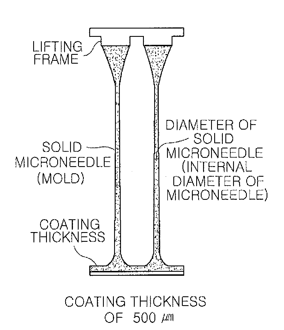
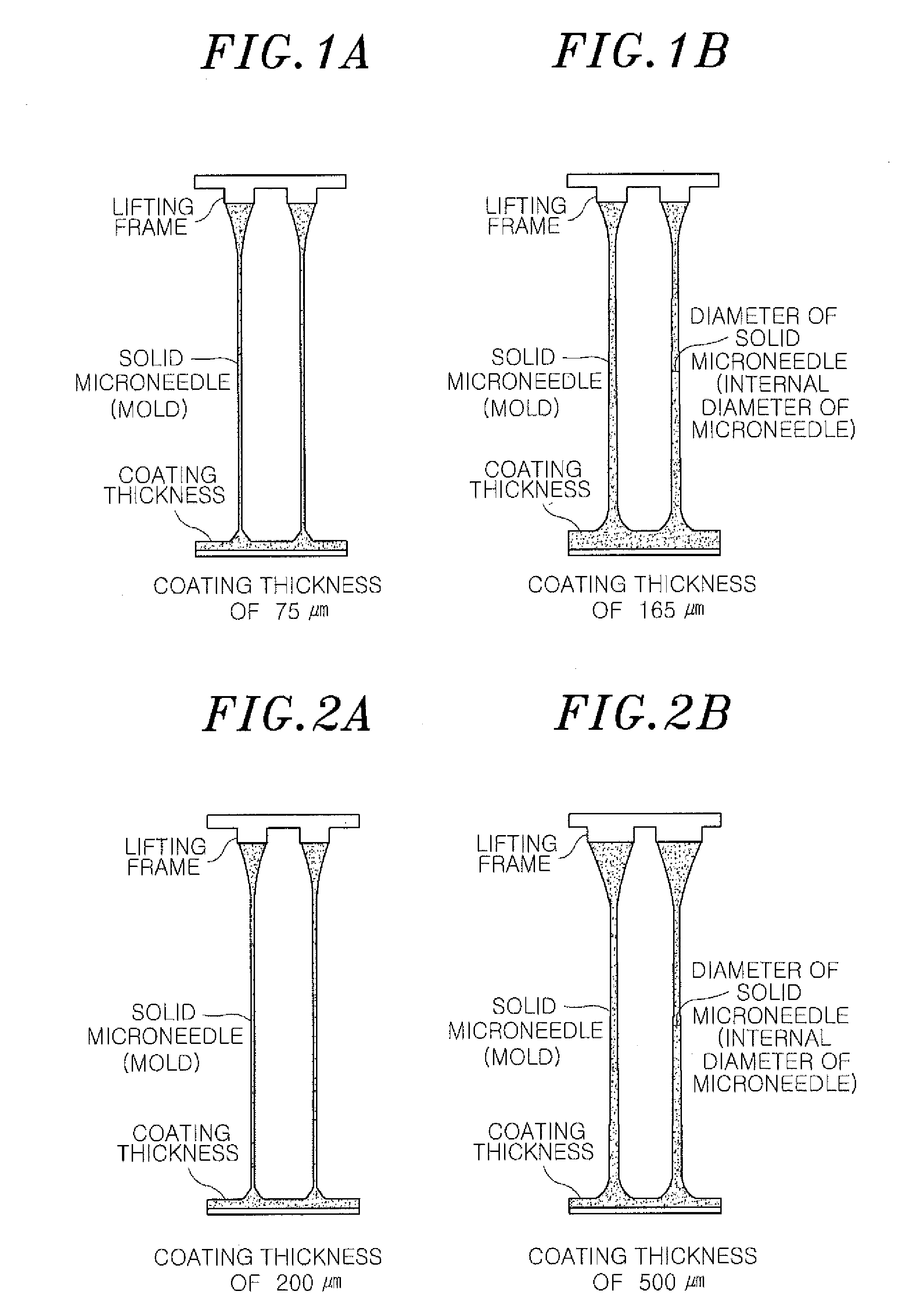
Varying an External Appearance of a Microneedle by Adjusting a Coating Thickness of a Polymer Solution

[0096]A solid microstructure is formed of an epoxy polymer “SU-8 2050 photoresist (microchem)” that is a polymer having viscosity of 14,000 cSt. SU-8 2050 is respectively coated on a metal or silicon substrate to a thickness of 75 μm and 165 μm, and then maintained at a temperature of 120° C. for 5 minutes, thereby enabling the flux of SU-8 2050 to be maintained. Subsequently, the SU-8 2050 is contacted to a 3×3 patterned frame having a diameter of 200 μm. While slowly lowering a temperature of the substrate to 70° C. to 60° C., the coated SU-8 2050 has viscosity enabling lifting. At this point, by lifting a lifting frame for 5 minutes at a speed of 10 μm / s, as illustrated in FIGS. 1A and 1B, an initial solid structure having a length of 3,000 μm is formed. By increasing a second lifting speed or cutting, the initial solid structure may be spaced apart from the lifting frame.

[0097]A...

embodiment 2

Varying an External Appearance of a Microneedle by Adjusting a Diameter of a Lifting Frame

[0099]A solid microstructure is formed of an epoxy polymer “SU-8 2050 photoresist” that is a polymer having viscosity of 14,000 cSt. SU-8 2050 is coated on a metal or silicon substrate to a thickness of 75 μm, and then maintained at a temperature of 120° C. for 5 minutes, thereby enabling the flux of the SU-8 2050 to be maintained. Subsequently, the SU-8 2050 is contacted to a 3×3 patterned frame having a diameter of 200 μm and a 3×3 patterned frame having a diameter of 500 μm, respectively. While slowly lowering a temperature of the substrate to 70° C. to 60° C., the coated SU-8 2050 has viscosity enabling lifting.

[0100]At this point, by lifting a lifting frame for 5 minutes at a speed of 10 μm / s, as illustrated in FIGS. 2A and 2B, an initial solid structure having a length of 3,000 μm is formed. By increasing a second lifting speed or cutting, the initial solid structure is spaced apart from ...

embodiment 3

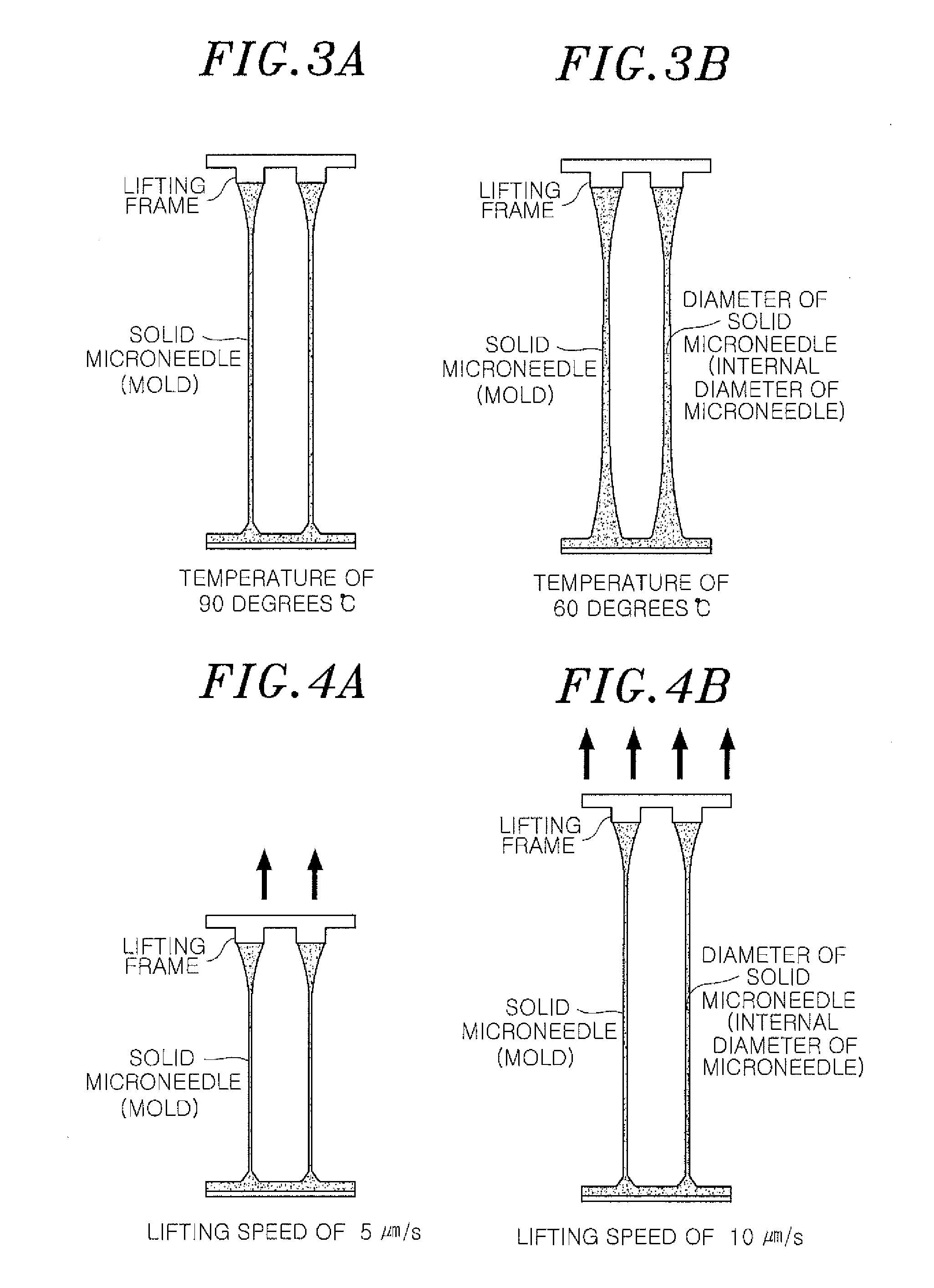
Varying an External Appearance of a Microneedle by Adjusting a Temperature

[0102]A solid microstructure is formed of an epoxy polymer “SU-8 2050 photoresist” that is a polymer having viscosity of 14,000 cSt. SU-8 2050 is coated on a metal or silicon substrate to a thickness of 75 μm, and then maintained at a temperature of 120° C. for 5 minutes, thereby enabling the flux of the SU-8 2050 to be maintained. Subsequently, the SU-8 2050 is contacted to a 3×3 patterned frame having a diameter of 200 μm. While slowly lowering a temperature of the substrate to 90° C. (adhesive strength of polymer: 1N, viscosity: 100 Poise) and 60° C. (adhesive strength of polymer: 2N, viscosity: 6,500 Poise), by lifting a lifting frame for 5 minutes at a speed of 10 μm / s, as illustrated in FIGS. 3A and 3B, an initial solid structure having a length of 3,000 μm is formed. By increasing a second lifting speed or cutting, the initial solid structure is spaced apart from the lifting frame. As a result, at an in...


PUM

PropertyMeasurementUnit
Lengthaaaaaaaaaa
Lengthaaaaaaaaaa
Angleaaaaaaaaaa

Abstract

The present invention relates to a method for fabricating a hollow microneedle having a variable appearance. The method makes it possible to vary the length of the microneedle, the outer and inner diameters of the upper and lower parts thereof, the aspect ratio, the sharpness, and the structural bending rate thereof, in accordance with the purposes of the same. Accordingly, the appearance of the hollow microneedles according to the present invention can be varied with flexibility according to various purposes, such as the transferring of medication and the taking of a blood sample, and to various factors, such as the target part for the medication transfer, the depth of the medication transfer, and the amount and viscosity of the medication. Thus, the microneedle can be used as a multi-purpose device for transferring medication.

Description

TECHNICAL FIELD[0001]The present invention relates to a method for manufacturing a hollow microneedle having a variable appearance and the hollow microneedle manufactured by the same.BACKGROUND ART[0002]Unlike the existing needles, micronneedles pass through skin without pain and do not leave an external injury. In order to implant a microneedle into skin without pain, a diameter of an upper portion of the microneedle is important for the minimum sharpness. Also, the microneedles needs to pass through a stratum corneum of 10 μm to 20 μm serving as the biggest obstacle in skin, and thus are required to have sufficient physical hardness. However, since the thicknesses and elasticity of skins, efficiency of transdermal drug delivery, the viscosities of drugs, and the amount of administered drugs differ according to species, races, individuals, and skin regions, a method for manufacturing a microneedle having a variable appearance is required.[0003]A hollow silicon microneedle having a ...

Claims


Application Information

Patent Timeline
IPC IPC(8): A61M5/00A61B5/1486B29D23/00A61F9/007
CPCA61M37/0015B81C1/00111A61M2037/0053A61B5/14865A61F9/00781A61M5/00B29D23/00G01N33/49A61B5/685A61B5/14532B81B2201/055B29C41/08B29L2031/7544B29C41/36B29C41/38A61K9/0021A61M2037/003
Inventor JUNG, HYUNG IILEE, KWANGCHO, SIN KILBYEON, YOUNG DOOK
Owner INCYTO
Why Eureka
Try Eureka