
Audio amplification circuit

a processing circuit and audio amplification technology, applied in the field of audio amplification and processing circuits, can solve the problems of thermal noise, failure damage or malfunction of active or passive components, etc., and achieve the effect of minimizing computational and hardware resource expenditure of audio amplification circuits, reducing the cost of hardware resources, and improving the masking of elevated input referred noise floors

Inactive Publication Date: 2013-05-23
ANALOG DEVICES GLOBAL
View PDF4 Cites 54 Cited by
  • Summary
  • Abstract
  • Description
  • Claims
  • Application Information

AI Technical Summary

Benefits of technology

The patent describes an audio amplification circuit that uses a common analog-to-digital converter for multiple amplified audio signals, reducing complexity and power consumption. The circuit keeps signal channels short and uses a single signal path for most of the signal processing, reducing space requirements. The semiconductor die or substrate on which this circuit is fabricated can be manufactured in a low-cost process, making it easy to produce the audio amplification circuit in large quantities.

Problems solved by technology

Furthermore, capacitors of the capacitive voltage do contribute with thermal noise to the audio input signal in contrast to a resistor based attenuator, in particular a high impedance attenuator required by the extremely large generator impedance of a condenser transducer element of a miniature ECM.
Overvoltage conditions may lead to destruction or malfunctioning of the active or passive components due to excessive substrate currents.
This type of overloading may result in long recovery or settling time of the first and / or second preamplifier(s) after the level of the audio input signal has returned to a level below the level causing the overload state.
This modulation of the transfer function or functions tend to impair an otherwise (for small signal operation) well-matched phase relationship between the first and second amplified audio signals.

Method used


Image

  • Audio amplification circuit
  • Audio amplification circuit
  • Audio amplification circuit

Examples


Embodiment Construction

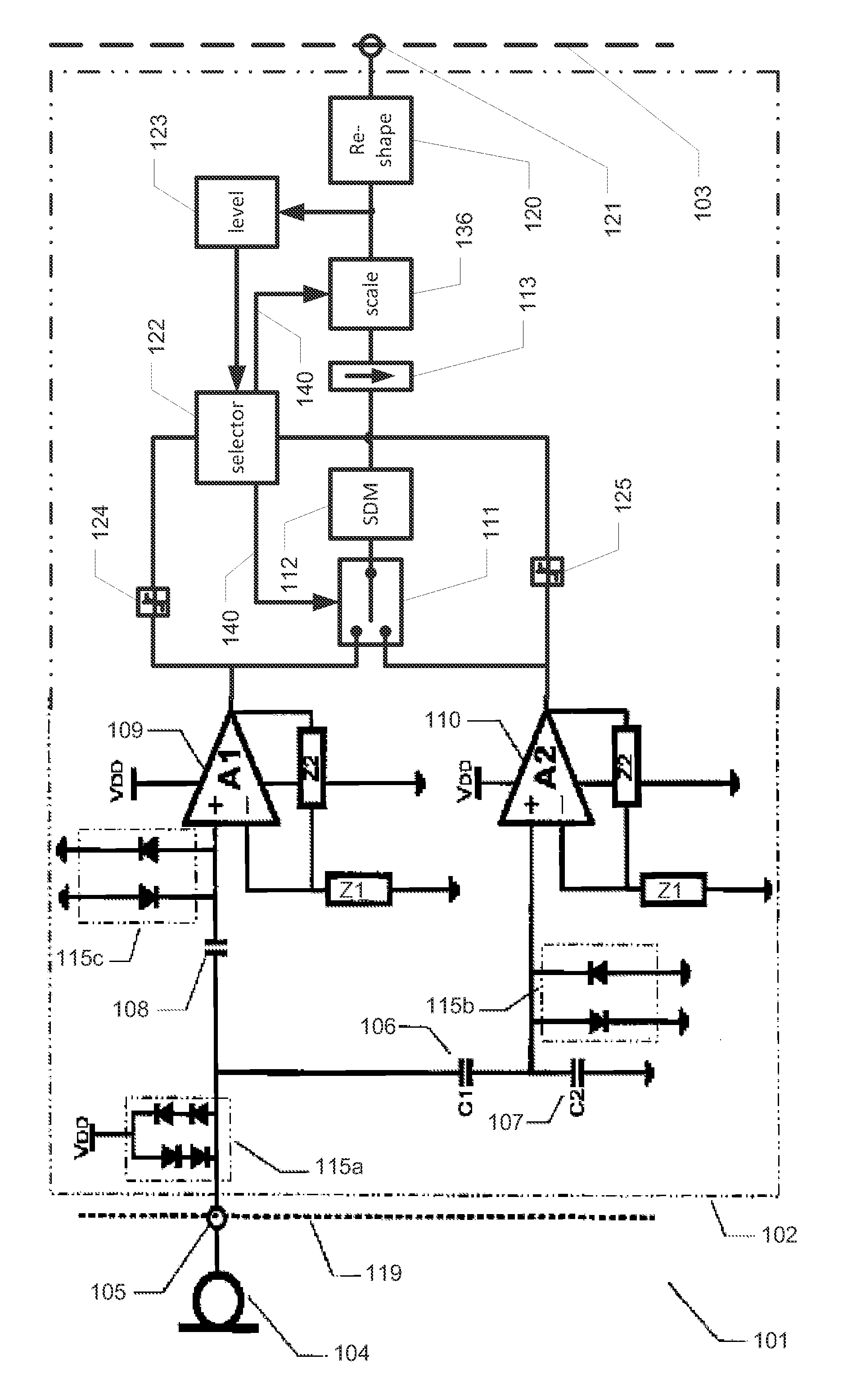
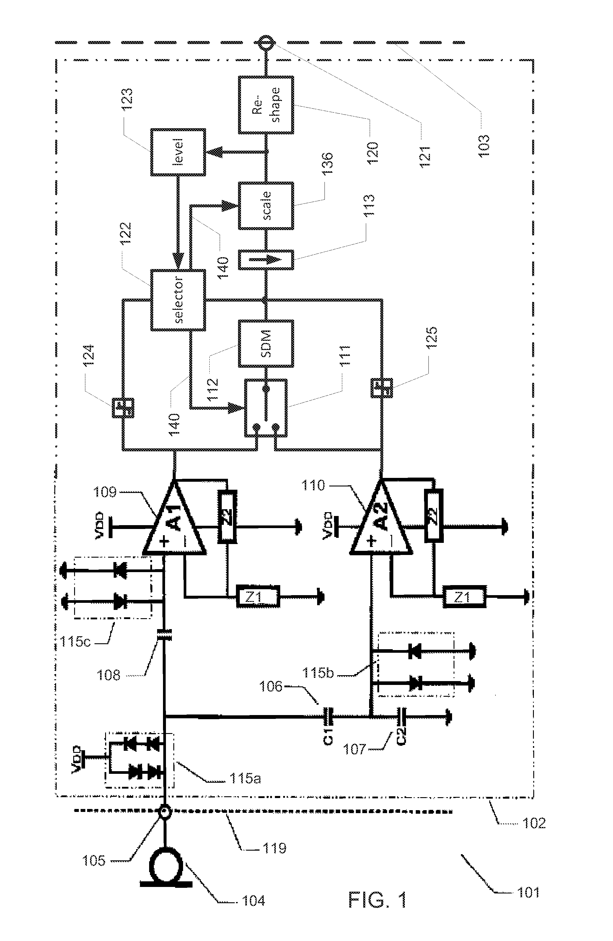
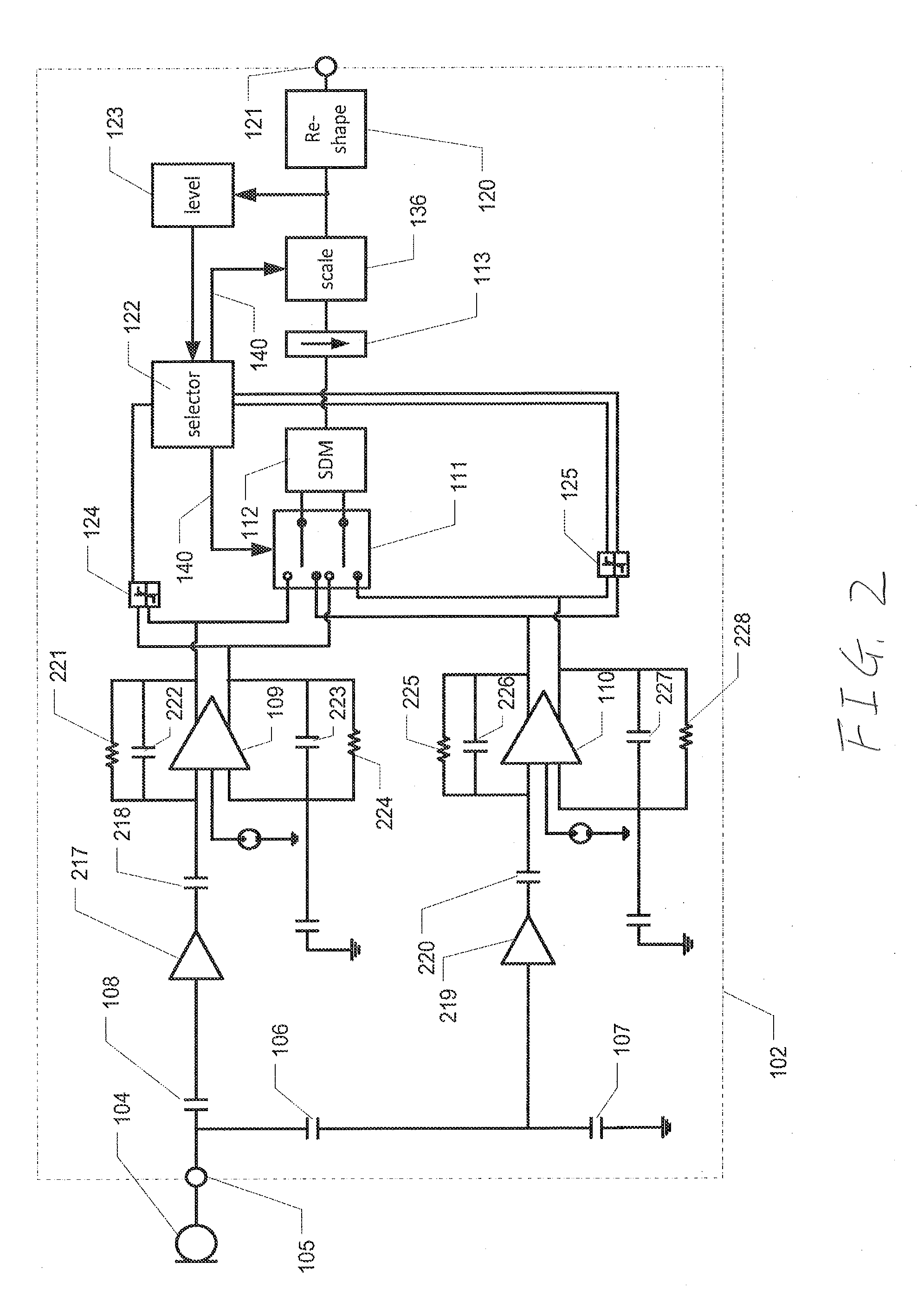
[0096]FIG. 1 is a schematic drawing of an audio amplification circuit system 101 which comprises a microphone and 104 an audio amplification circuit 102 according to a first embodiment. The audio amplification circuit may serve as a front-end of a subsequent audio signal processing circuit (not shown). As illustrated by dashed interface line 103, the audio amplification circuit 102 may either be fabricated or implemented on separate CMOS semiconductor die or it may be fabricated on a common CMOS semiconductor die together with a subsequent signal processing circuit. A separate audio signal processing circuit may reside remotely for example within a portable terminal in form of an appropriately programmed or configured Digital Signal Processor (DSP) with data interface terminal(s) operatively coupled to the illustrated externally accessible output terminal 121 of the present audio amplification circuit 102 for receipt of a digital audio signal or digital audio stream. In this configu...


PUM


Abstract

Disclosed is an audio amplification circuit comprising: an input terminal for receipt of an audio input signal; a first preamplifier having an input operatively coupled to the input terminal and operable to provide a first amplified audio signal with a first signal amplification; a second preamplifier having an input operatively coupled to the input terminal and operable to provide a second amplified audio signal with a second signal amplification, smaller than the first signal amplification; a switch having a first input operatively coupled to the first preamplifier, a second input operatively coupled to the second preamplifier, and an output; an analogue-to-digital converter operatively coupled to the output of the switch and operable to provide a digital audio signal; a signal selection circuit operable to control the switch to selectively provide one of the first and second amplified audio signals on the output of the switch.

Description

[0001]The present invention benefits from priority afforded by U.S. patent application Ser. No. 61 / 562,168, entitled “Audio Amplification Circuit,” filed Nov. 21, 2011, the disclosure of which is incorporated herein in its entirety.[0002]The present invention relates to an audio amplification circuit with first and second signal channels with different signal amplifications based on a common audio input signal. The invention also relates to a method of amplifying a common audio input signal with different signal amplifications to provide first and second audio signals with different amplification. The invention further relates to a semiconductor die or substrate comprising such an audio amplification circuit and a miniature capacitive microphone comprising such an audio amplification circuit.BACKGROUND[0003]Acceptable handling of audio signals with very large dynamic range presents significant challenges to audio amplification and processing circuits and systems, in particular for a...

Claims


Application Information

Patent Timeline
IPC IPC(8): H04R3/00
CPCH04R3/00H04R3/06H03F3/187H04R2460/03H03F1/52H04R19/005
Inventor THOMSEN, HENRIKHANSEN, KRISTIANHENRIKSEN, JENS
Owner ANALOG DEVICES GLOBAL
Learn More