Prevention of post-pecvd vacuum and abatement system fouling using a fluorine containing cleaning gas chamber

a technology of cleaning gas chamber, which is applied in the direction of cleaning process, equipment, coatings, etc., can solve the problems of affecting the cleaning effect of the device being manufactured, unwanted deposits can also be formed downstream of the chamber, and other undesirable effects, so as to reduce the cleaning time of the chamber and improve the cleaning effect. , the effect of reducing the fouling of the vacuum and abatement system

Inactive Publication Date: 2013-05-30
LINDE AG
View PDF4 Cites 19 Cited by
  • Summary
  • Abstract
  • Description
  • Claims
  • Application Information

AI Technical Summary

Benefits of technology

[0006]The present invention provides methods and apparatus for reducing post PECVD vacuum and abatement system fouling. By using the present invention, chamber cleaning times can be reduced leading to increased efficiency and lower cost fabrication processes. The advantages of the present invention are accomplished by introducing F2 or a fluorine containing gas such as F2, NF3 or SF6 into the PECVD system. The cleaning gas may be introduced at different locations of the PECVD system and therefore target specific area and components of the system to avoid fouling. When using F2 as the cleaning gas, the F2 may be introduced directly to the targeted area or component where it can interact without activation with any unwanted deposits or materials. Alternatively, the cleaning gas, e.g. F2, NF3 or SF6, may be activated in-situ in areas or components where plasma discharge equipment is already in place or in further alternatives, the cleaning gas e.g. F2, NF3 or SF6, may be activated using an RPS and then introduced to the targeted area or component in its already activated state.

Problems solved by technology

However, the activated plasma species do not only react with the substrate, but rather also deposit on the surfaces of the vacuum chamber, which can lead to contamination of subsequent substrates with undesired chemical reactants or particles that can degrade the function of the device being fabricated.
In addition, to the deposits formed in the chamber, unwanted deposits can also be formed downstream of the chamber, for example, in the vacuum pump or abatement equipment for the system or in conduits connected thereto.
While these downstream deposits do not pose the same deleterious effects on subsequent substrate processing in the chamber, they can lead to other undesirable effects, generally referred to as fouling.
For example, these downstream deposits can restrict the vacuum conductance, abrasive particles may harm the vacuum pump or abatement equipment, and chemical reactions may heat and harm the vacuum pump, abatement equipment or their associated conduits.
When forming tandem junction or for micromorph PV processes, where a relatively thick layer (>1 μm) of microcrystalline silicon is deposited, fouling can create a significant risk to manufacturing efficiency because of the amount of reactive material that can accumulate during a single deposition cycle.
While the downstream deposits can also be removed using the cleaning gases noted above, because these areas are downstream of the vacuum chamber, they are cleaned after the chamber cleaning and therefore extend the cleaning cycle resulting in greater down time and lower productivity.
In addition, the typical endpoint detection means are not effective in these downstream areas of the system and the inability to monitor the endpoint can result in either incomplete cleaning and deposit accumulation or running the cleaning cycle too long and wasting time and material.
Also, because these deposits accumulate unevenly, there is the possibility that enough material will accumulate in a particular area that the cleaning process will result in deleterious localized heating.

Method used


Image

  • Prevention of post-pecvd vacuum and abatement system fouling using a fluorine containing cleaning gas chamber
  • Prevention of post-pecvd vacuum and abatement system fouling using a fluorine containing cleaning gas chamber

Examples


Embodiment Construction

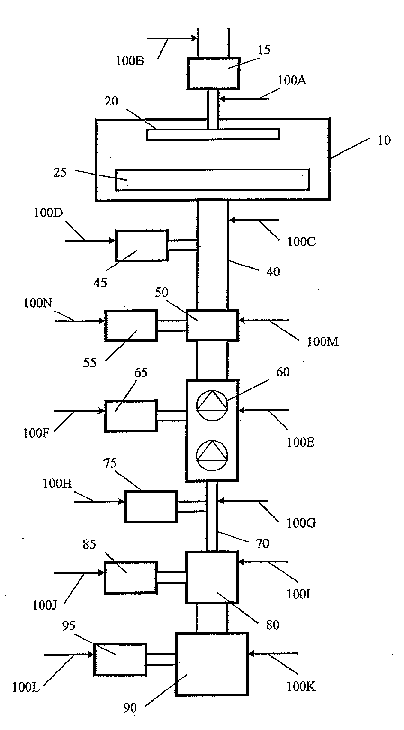
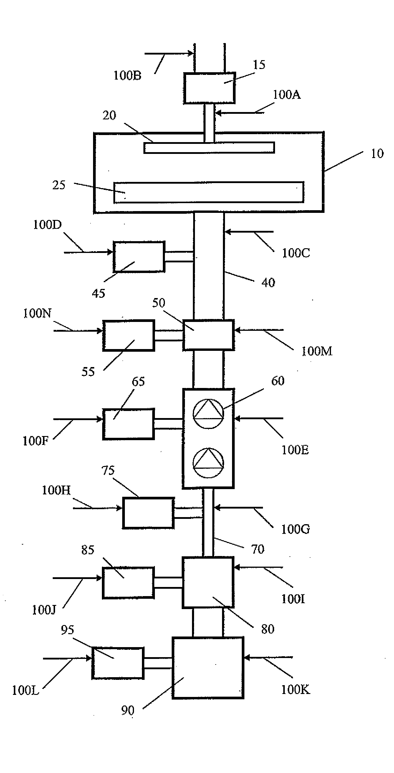
[0008]The present invention provides methods and apparatus for reducing post PECVD vacuum and abatement system fouling. Processes for the fabrication of thin films and thin film devices can be improved by utilizing the present invention, wherein chamber and equipment cleaning times can be reduced leading to increased efficiency and lower costs. In general, the present invention provides these advantages by introducing F2 or a fluorine containing gas into the PECVD system. The cleaning gas can be introduced at a number of different locations throughout the system and in a number of different ways, as will be more fully described below with reference to the drawing FIGURE.

[0009]The FIGURE is a schematic drawing of a PECVD system according to the present invention, including a deposition chamber 10 having plasma discharge equipment 20, 25 for activation of the deposition gases. The deposition chamber 10 is fluidly connected with a vacuum pump system 60 through a vacuum pump foreline 40...


PUM

PropertyMeasurementUnit
thickaaaaaaaaaa
foulingaaaaaaaaaa
energyaaaaaaaaaa

Abstract

Methods and apparatus for reducing post PECVD vacuum and abatement system fouling. Chamber cleaning times are reduced leading to increased efficiency and lower cost fabrication processes by introducing F2 or a fluorine containing gas into the PECVD system. When using F2, the cleaning gas may be introduced directly to desired locations of the system where it can interact without activation with unwanted deposits. Alternatively, the cleaning gas may be activated in-situ in the equipment using existing plasma discharge equipment, or the cleaning gas may be activated using an RPS and then introduced to the desired location in its already activated state.

Description

BACKGROUND OF THE INVENTION[0001]Thin film deposition processes for depositing films of pure and compound materials are known. In recent years, the dominant technique for thin film deposition has been chemical vapor deposition (CVD). A variant of CVD, Plasma Enhanced Chemical Vapor Deposition (PECVD) has been used to manufactured thin-film devices such as integrated circuits, liquid crystal displays and photovoltaic panels. A standard PECVD technique comprising introducing gaseous precursor materials, such as silane and hydrogen, into a vacuum deposition chamber and activating the gases using a plasma discharge device. The energy from the plasma discharge breaks the molecular bonds of the precursor gases resulting in a plasma containing both neutral radical and charged ionic atoms and molecular fragments. Thin films of material, such as silicon, can then be formed on the surface of a substrate, such as a wafer or glass sheet, as the activated plasma reacts with the substrate. Proces...

Claims


Application Information

Patent Timeline
Patent Type & Authority Applications(United States)
IPC IPC(8): B08B17/02
CPCB08B17/02B08B7/0035C23C16/4412C23C16/4405
Inventor STOCKMAN, PAUL A.HOGLE, RICHARDMANNLING, HANS-DIETERTRAVIS, IAN
Owner LINDE AG
Why Eureka
Try Eureka