Modular stacked DC architecture traction system and method of making same

Active Publication Date: 2013-05-30
GENERAL ELECTRIC CO
View PDF4 Cites 3 Cited by
  • Summary
  • Abstract
  • Description
  • Claims
  • Application Information

AI Technical Summary

Benefits of technology

[0009]It would therefore be desirable to provide an apparatus for coupling the low

Problems solved by technology

A high voltage ES element having several cells in series often experiences less-than-optimal cell voltage balanci

Method used


Image

  • Modular stacked DC architecture traction system and method of making same
  • Modular stacked DC architecture traction system and method of making same
  • Modular stacked DC architecture traction system and method of making same

Examples


Example

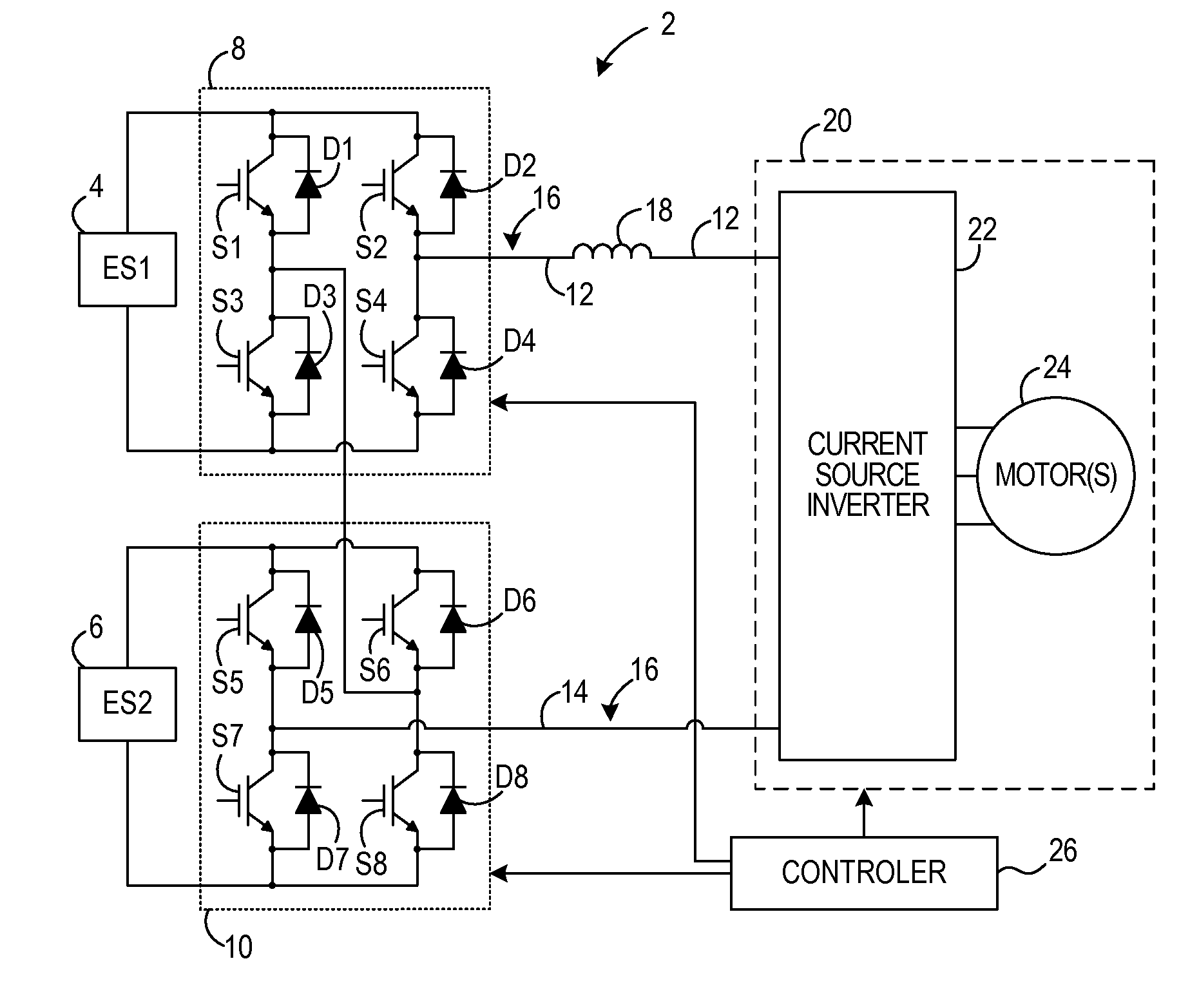
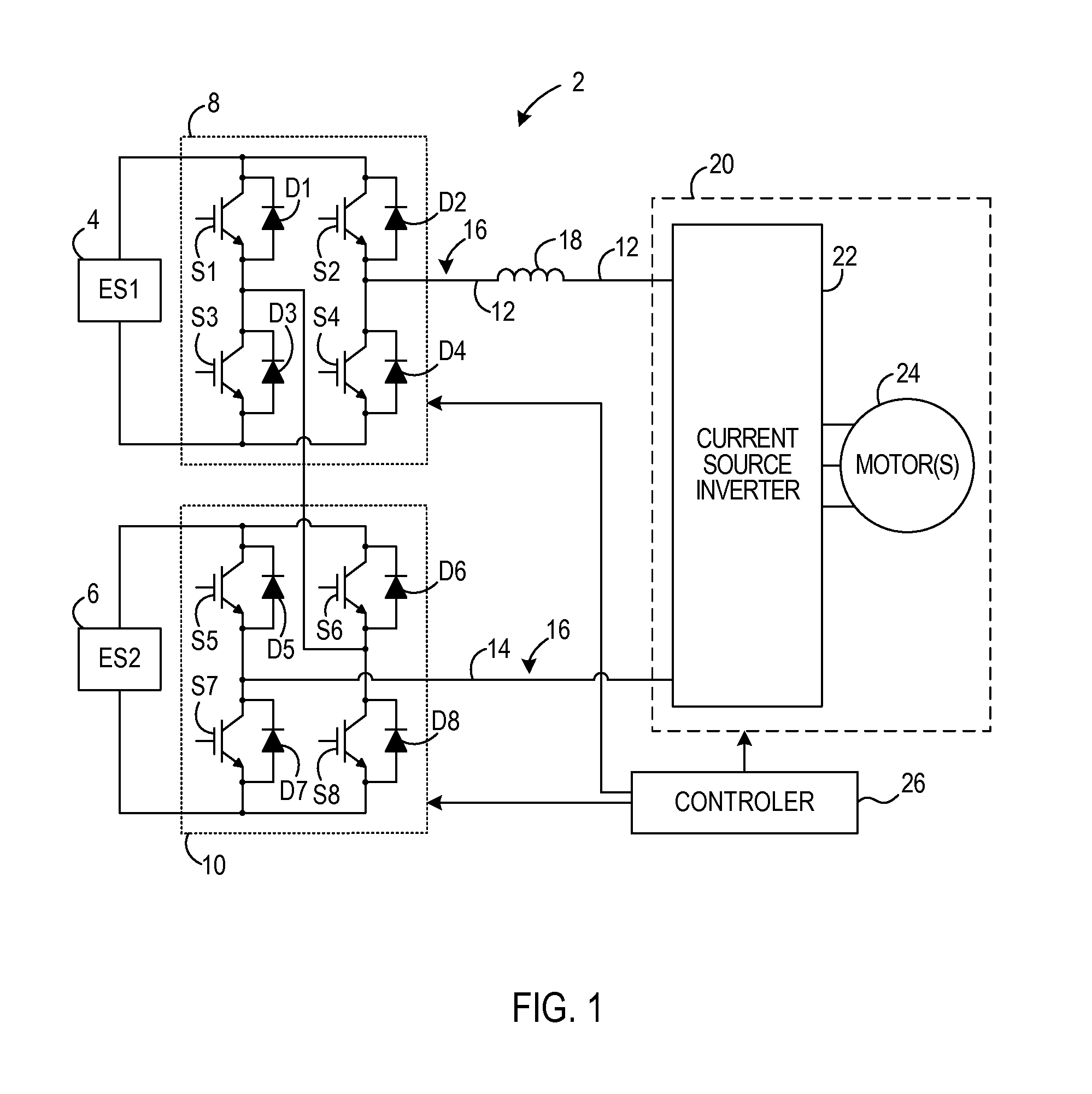
[0023]FIG. 1 illustrates a modular stacked DC architecture traction / propulsion system 2 in accordance with an embodiment of the invention. Traction system 2 includes a first energy storage device (ES1) 4 and a second energy storage device (ES2) 6. In embodiments of the invention, ES14 and ES26 are low voltage, high specific-energy storage devices, and each may be, for example, an ultracapacitor or an energy battery. In this case, an ultracapacitor represents a capacitor comprising multiple capacitor cells coupled to one another, where the capacitor cells may each have a capacitance that is greater than 500 Farads. The term energy battery used in the embodiments shown herein describes a high specific-energy battery or high energy density battery demonstrated to achieve an energy density on the order of 100 W-hr / kg or greater (e.g., a Li-ion, sodium-metal halide, sodium nickel chloride, sodium-sulfur, zinc-air, nickel metal halide, or lead acid battery, or the like).

[0024]ES14 and ES2...


PUM

PropertyMeasurementUnit
Poweraaaaaaaaaa
Currentaaaaaaaaaa
Energyaaaaaaaaaa

Abstract

A modular stacked DC architecture for traction system includes a propulsion system includes an electric drive, a direct current (DC) link electrically coupled to the electric drive, and a first DC-DC converter coupled to the DC link. A first energy storage device (ESD) is electrically coupled to the first DC-DC converter, and a second DC-DC converter is coupled to the DC link and to the first DC-DC converter. The system also includes a second energy storage device electrically coupled to the second DC-DC converter and a controller coupled to the first and second DC-DC converters and configured to control a transfer of energy between the first ESD and the DC link via the first and second DC-DC converters.

Description

BACKGROUND OF THE INVENTION[0001]Embodiments of the invention relate generally to hybrid and electric vehicles and, more particularly, to a modular stacked direct current (DC) architecture traction system for hybrid and electric vehicles.[0002]A hybrid electric vehicle (HEV) may combine an internal combustion engine and an electric motor powered by an energy storage device, such as a traction battery, to propel the vehicle. Typically, the electric motor of an HEV is coupled between the internal combustion engine and the transmission to take advantage of the torque increase through the transmission. Such a combination may increase overall fuel efficiency by enabling the combustion engine and the electric motor to each operate in respective ranges of increased efficiency. Electric motors, for example, may be efficient at accelerating from a standing start, while combustion engines may be efficient during sustained periods of constant engine operation, such as in highway driving. Havin...

Claims


Application Information

Patent Timeline
IPC IPC(8): H02P6/08H01R43/00
CPCH02P27/14Y02T10/7005Y02T10/7022Y02T10/7066Y02T10/7061Y10T29/49117B60L11/005B60L11/1853B60L11/1866B60L11/1868B60L15/007Y02T10/644B60L50/40B60L58/18B60L58/20B60L58/22Y02T10/64Y02T10/70B60L2210/10B60L2240/54B60Y2300/91B60Y2400/112H02P27/06H05K13/00
Inventor KANAKASABAI, VISWANATHANSEN, BHASKAR
Owner GENERAL ELECTRIC CO
Why Eureka
Try Eureka