
System, devices, and methods for optically clearing tissue

a tissue optical and optical technology, applied in the field of manipulating the optical properties of tissue, can solve the problems of desired irreversible destruction and scattering strength, and achieve the effects of reducing the scattering strength of engineered human skin optical properties, reducing light scattering in skin, and increasing fluen

Active Publication Date: 2013-07-11
BOARD OF RGT THE UNIV OF TEXAS SYST
View PDF5 Cites 22 Cited by
  • Summary
  • Abstract
  • Description
  • Claims
  • Application Information

AI Technical Summary

Benefits of technology

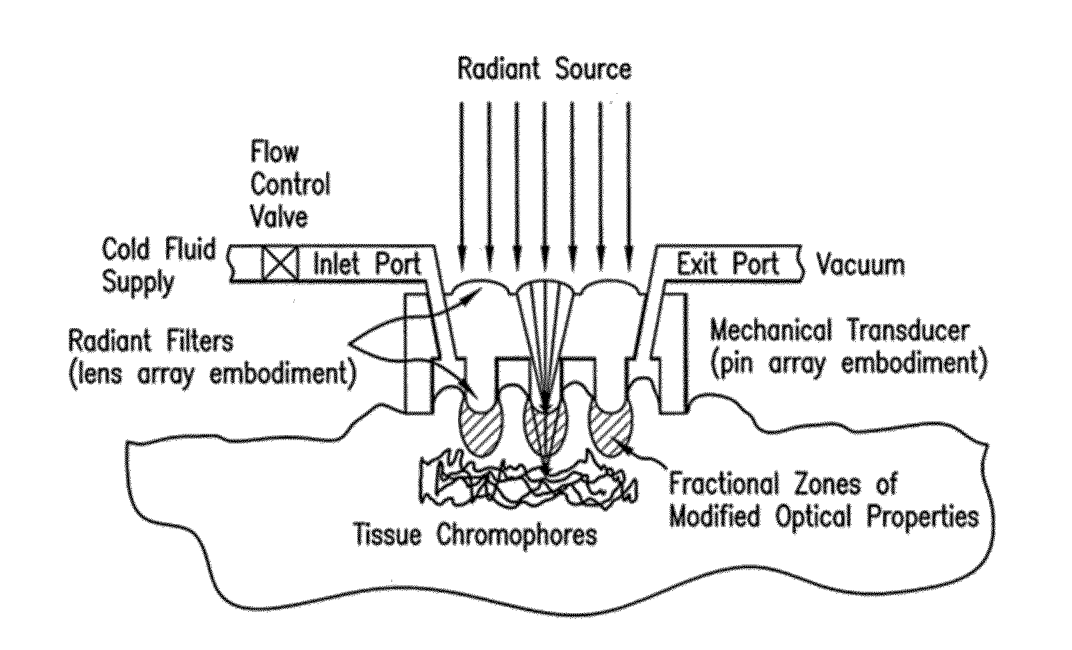
The patent text is about a need for systems, devices, methods, compositions, and kits to reduce light scattering in skin. This would help in various light-based therapeutic and diagnostic methods by increasing the fluence delivered to a target chromophore. The methods and devices mentioned in the text are non-invasive, safe, and fast. They may use dynamic feedback and physically integrate with a light delivery hand-piece. The techniques described in the patent may make tissue (e.g., skin) more optically transparent for medical imaging and therapeutic light treatments. The patent presents various forms of mechanical devices that can vary the geometry of the tissue-device interface, allowing for unique light administration to the tissue for different purposes such as hair removal, adipose contouring, removal, or reduction, and fat reduction.

Problems solved by technology

A decrease in scattering strength of engineered human skin optical properties may impact light-based therapeutics by increasing the fluence delivered to a target chromophore, resulting in desired irreversible destruction.

Method used


Image

  • System, devices, and methods for optically clearing tissue
  • System, devices, and methods for optically clearing tissue
  • System, devices, and methods for optically clearing tissue

Examples


example 1

Observations on Human Skin

[0163]The device was applied to the bottom of the lower arm and pressed into the skin. Observations may be possible through the applied device and after device removal.

[0164]Pressing the device onto the skin without vacuum caused some reddening of the tissue surrounding the pins. This was caused by the displacement of blood from underneath the pins. Skin under the pins turned pale in appearance. After removal of the device the previously described skin color changes persisted for several seconds before pale, blood-voided skin slowly became more red and the increased red appearance of peripheral tissue decreased.

[0165]Applying a vacuum of ˜750 mm Hg added significantly to the benefits of the device. The mechanical stress on the tissue underneath the pins was noticeably increased, resulting in better stretch and more complete conformation of the skin around each pin. This added mechanical influence caused more complete displacement of interstitial tissue wate...

example 2

Unaided Eye Observations on In Vitro Pig Skin

[0169]The advantage of using in vitro tissue may be the ability to observe transmitted light through the specimen. Porcine skin may be comparable to human skin and was used for this experiment. The sample was previously snap frozen in liquid nitrogen and allowed to thaw at 25° C. The epidermis was highly pigmented and therefore significantly attenuated visible light transmission, cf. FIGS. 9(a) and (b).

[0170]However, as the Example Device No. 1 was applied to the skin, locally increased light transmission was immediately apparent. Removal of the device from the skin after a few seconds allowed direct visualization of locally increased light transport through the tissue, which was compressed and mechanically dehydrated by the pins.

[0171]Similarly, digital photographs may be acquired using in vitro porcine skin while device no. 1 was applied to the skin surface. Light from a broadband CW white light source was transmitted through the tissue...

example 3

Optical Coherence Tomography Measurements at 1290 nm on In Vivo Human Skin

[0174]Optical coherence tomography as a non-invasive imaging modality may be a very useful tool in assessing not only skin deformation and compression due to the device but also to analyze improved light transport within the compressed tissue. Acquisition of lateral cross-sectional images of tissue permitted observation of the contrasting light propagation in tissue underneath pins and between pins. The following OCT images may be acquired on the lower arm of human subjects.

[0175]For easier comparison of the OCT imaging depth the original image shown on the top of each figure was digitally processed in order to re-register the tissue surface to a common flat level shown in the bottom part of each figure. OCT images in FIGS. 12(a) and (b) may be acquired with device no. 3 and nicely illustrate the enhanced light penetration depth in areas of previously compressed tissue. The image in FIG. 12(a) was obtained fro...


PUM


Abstract

Embodiments of the present disclosure provides systems, devices, and methods for non-invasively modifying, maintaining, or controlling local tissue optical properties. Methods and devices of the disclosure may be used for optically clearing tissue, for example, for diagnostic and / or therapeutic purposes. A method of optically clearing a tissue may comprise contacting the tissue with an optical clearing device having a base, an array of pins fixed to one side of the base, a brim fixed to the base, an inlet port in the base, an exit port in the base, and a handpiece interface tab fixed to the side of the base opposite the array of pins, applying a mechanical force to the tissue, and illuminating said tissue with at least one wavelength of light through the optical clearing device. A method may further comprise controlling the temperature of the tissue illuminated.

Description

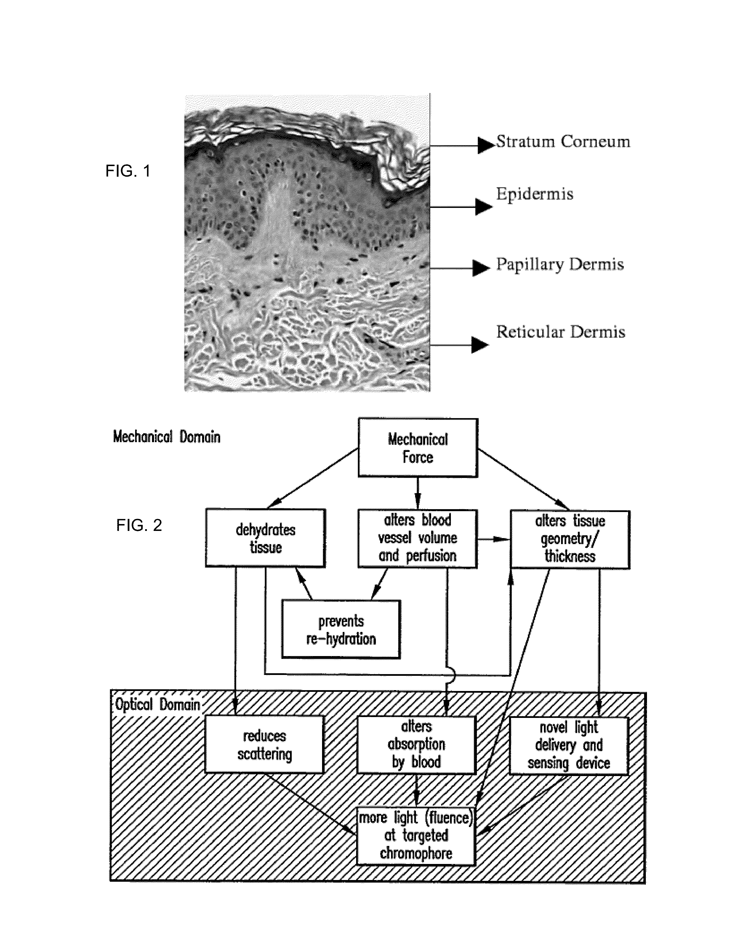
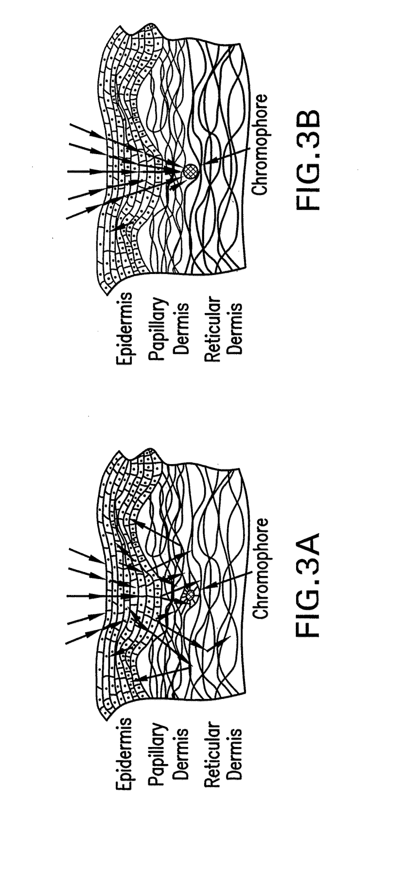
CROSS-REFERENCE TO RELATED APPLICATIONS[0001]This application is a divisional application from U.S. patent application Ser. No. 11 / 502,687, filed Aug. 12, 2006, which claims the benefit of U.S. Provisional Patent Application Ser. No. 60 / 707,778, filed Aug. 12, 2005, all of which are incorporated herein in their entirety by reference.STATEMENT OF GOVERNMENT INTEREST[0002]This disclosure was supported in part by funding from the National Science Foundation, Grant Nos. 9986296 and 9870653. The U.S. Government may have certain rights in the invention.BACKGROUND[0003]The present disclosure relates to manipulating the optical properties of tissue for diagnostic and / or therapeutic advantage.[0004]The specific morphology of human skin as well as other biological tissues gives rise to scattering of light. Skin may be the largest organ in the human body and composed of three distinct structures, as shown, for example, in FIG. 1. From the surface downward, they may be: 1) the epidermis; 2) der...

Claims


Application Information

Patent Timeline
Patent Type & Authority Applications(United States)
IPC IPC(8): A61N5/06
CPCA61B5/0066A61N2005/063A61B5/0071A61B5/0075A61B5/444A61B18/14A61B18/1815A61B18/203A61B2017/306A61B2018/00029A61B2018/00035A61B2018/00452A61N2005/0649A61B2018/00994A61N5/06A61N5/0616A61N5/062A61B5/0068A61B2018/00809
Inventor RYLANDER, CHRISTOPHER G.MILNER, THOMAS E.STUMPP, OLIVERNELSON, J. STUART
Owner BOARD OF RGT THE UNIV OF TEXAS SYST
Learn More