
Stents with low strut thickness and variable strut geometry

a stent and strut technology, applied in the field of balloon expandable stents, can solve the problems of different crossing profiles in deferent sections of the stent, tissue prolapse, restonosis or embolism, etc., and achieve the effect of reducing the thickness of the stent strut, and enhancing the overall structure of the sten

Inactive Publication Date: 2013-07-11
MERIL LIFE SCI PVT
View PDF13 Cites 26 Cited by
  • Summary
  • Abstract
  • Description
  • Claims
  • Application Information

AI Technical Summary

Benefits of technology

The present invention relates to a stent with a scaffold structure that has different geometry across its axial length to achieve different radial strengths and different expansion characteristics. The scaffold structure of at least one end section is designed to have higher mechanical strength compared to the central section. This differential strength is achieved without affecting other properties of the stent. The stent can be designed for different applications like coronary or cerebral vasculature by varying the shapes and dimensions of the elements of the stent. The stent structure configuration described in this invention gives enough flexibility to a stent designer to tailor the stent for any application.

Problems solved by technology

Very wide cross section will lead to a relatively open structure which can not contain the plaque effectively leading to tissue prolapse resulting into restenosis or embolization.
Another disadvantage is different crossing profiles in deferent sections of the stent.
Using different materials in the same stent makes its construction quite difficult and tedious.
In addition, it may lead to galvanic corrosion.
Increasing the width of the struts is not very effective in increasing the strength as the section modulus is directly proportional to its width and the width of the stent strut can not be increased beyond a limit where the strut will start touching each other during crimping on the balloon catheter.
It is tedious and difficult to apply differential heat treatment to different parts of the stent across its axis.

Method used


Image

  • Stents with low strut thickness and variable strut geometry
  • Stents with low strut thickness and variable strut geometry
  • Stents with low strut thickness and variable strut geometry

Examples


Embodiment Construction

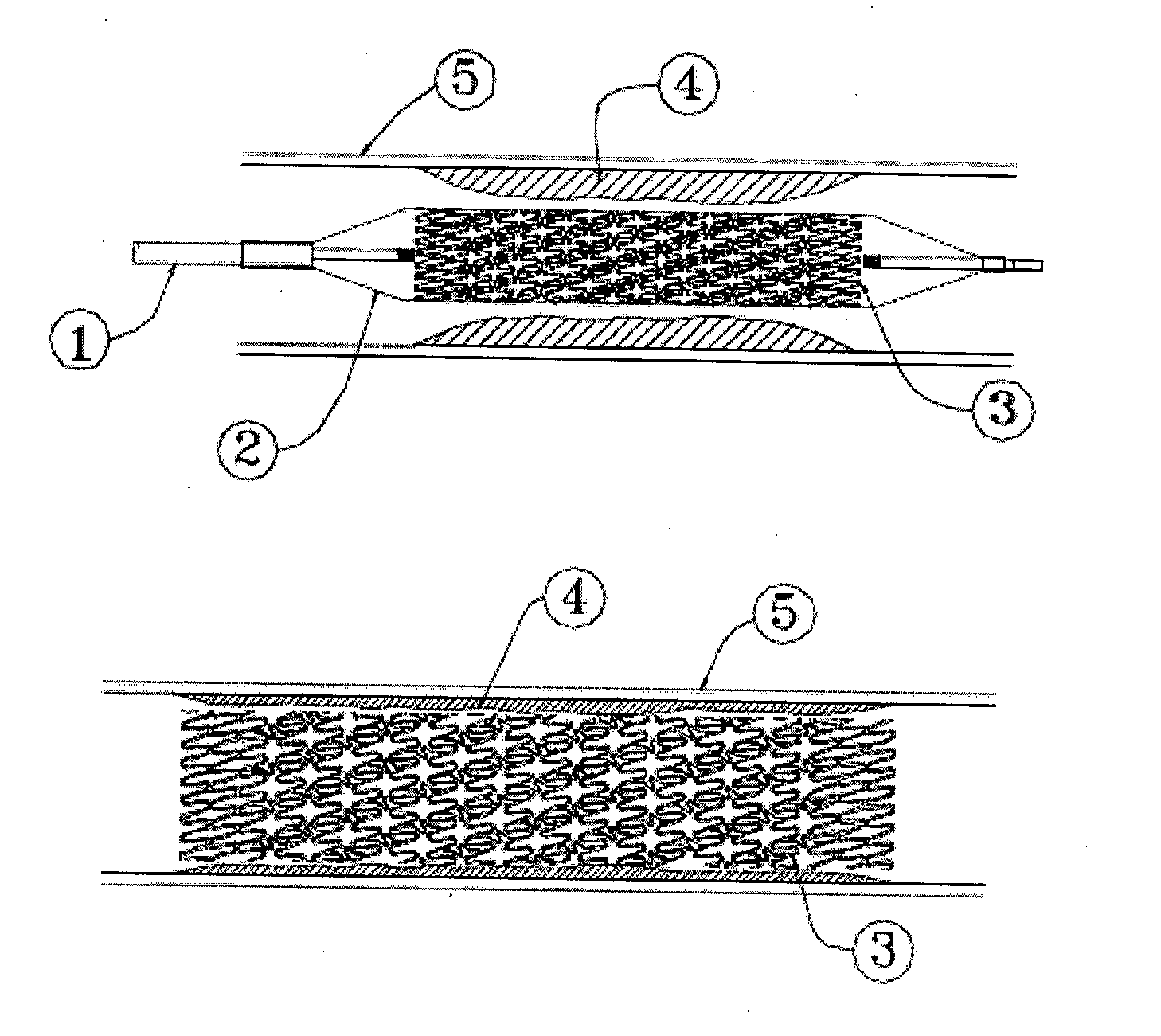
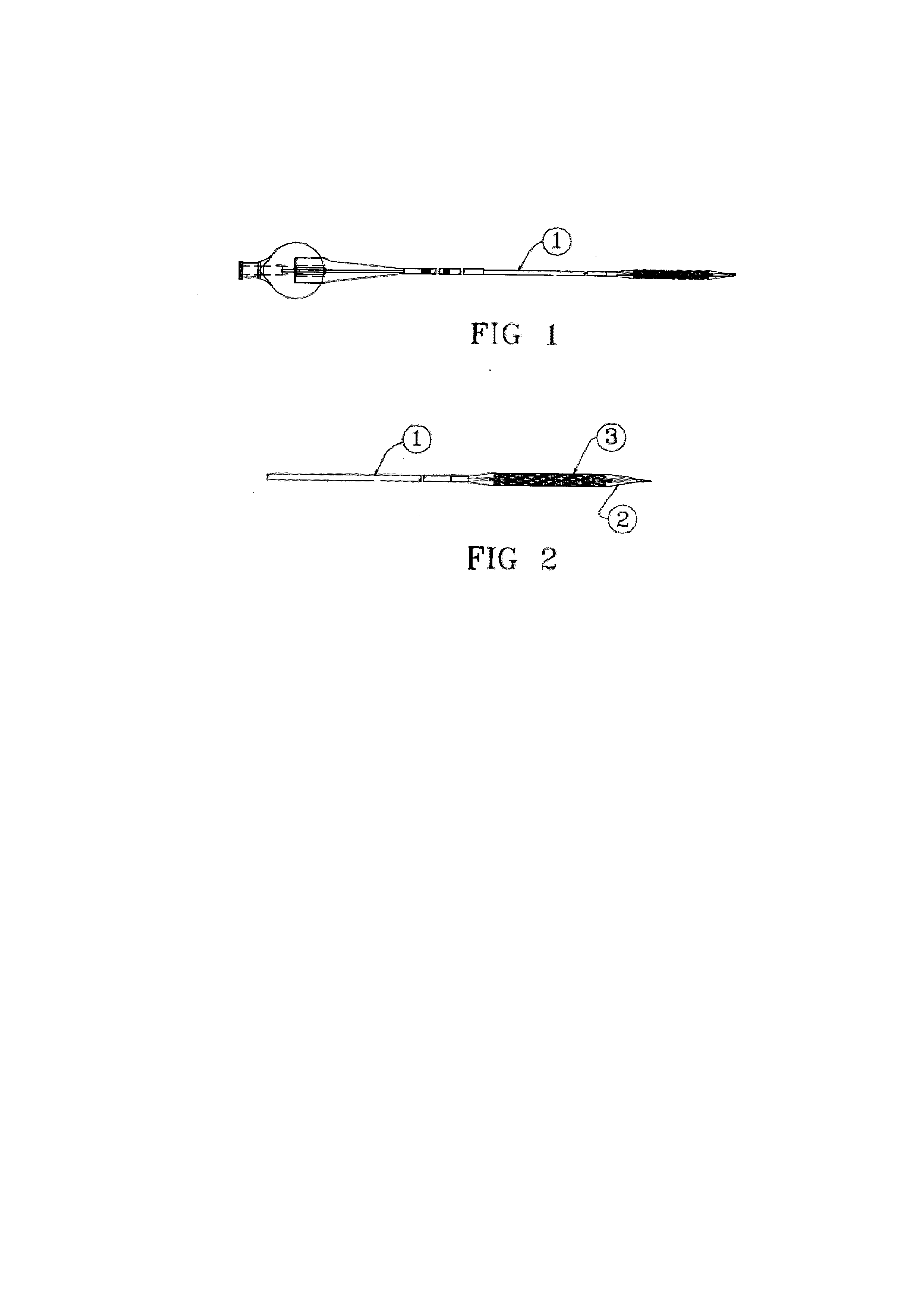
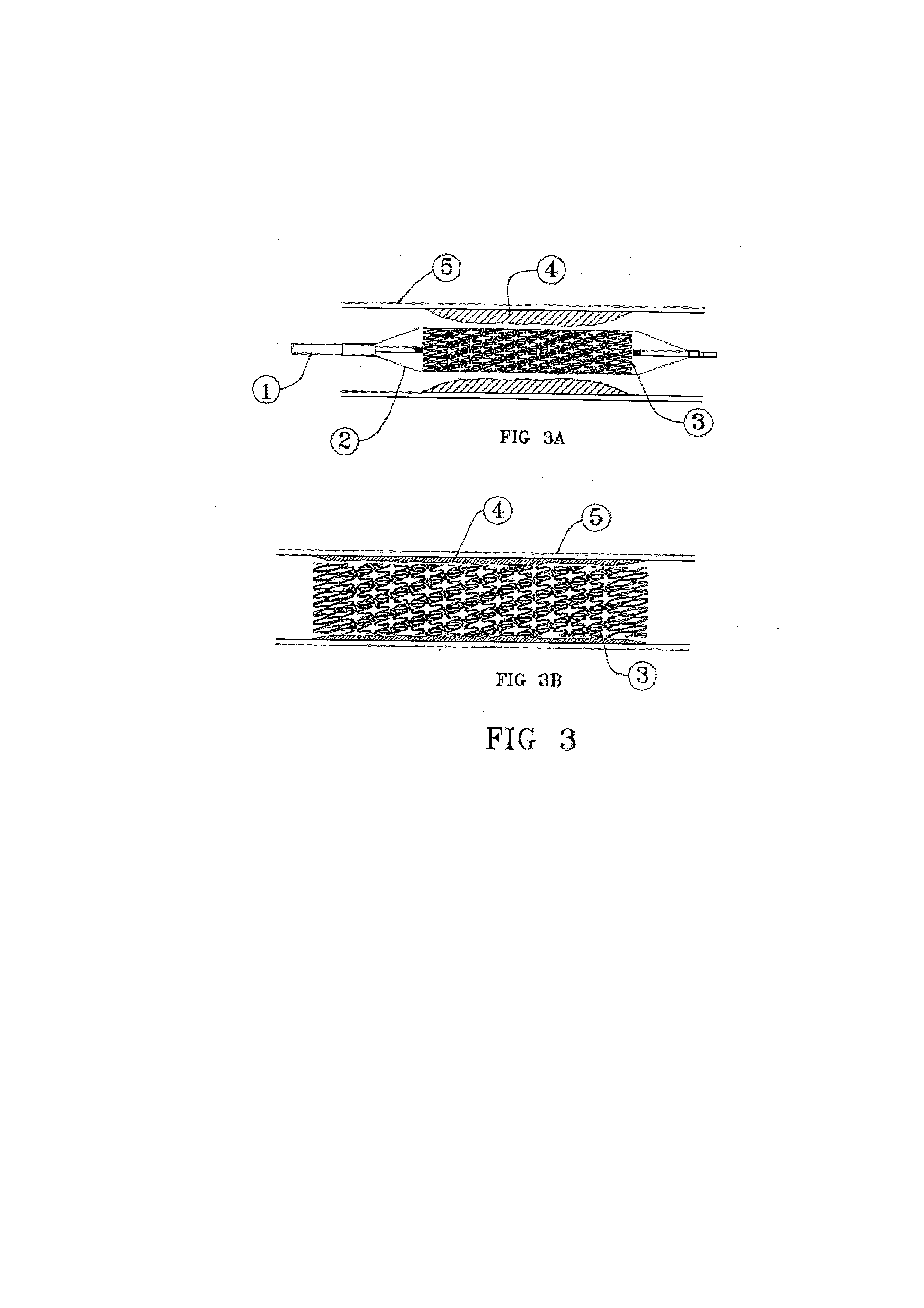
[0057]As shown in FIGS. 1 through 4, the preferred embodiment of the present invention includes stent 3 consisting of central section 8 and identical end sections 6 and 7 along the longitudinal axis of the stent. All the sections have expandable strut elements 9′, 9″, 12′, 12″ and 13 having a plurality of sinusoidal wave shaped sections 9 (closed) and 12 (open) linked in specific manner by direct connections or through “s” shaped linkages to form entire body of the stent. The sinusoidal shaped closed cells 9 have struts 9′ and 9″ as shown in FIG. 5. The sinusoidal shaped open cells 12 have struts 12′ and 12″ as shown in FIG. 6. The struts 9′ and 9″ of closed cells 9 are interconnected with each other across their length forming a joint 11 and at their tips forming a joint 10 as shown in FIG. 5. The open cell 12 in one row is joined to another open cell 14 in the next row by “s” shaped interconnecting link 13 as shown in FIG. 6. The width of the struts 9′, 9″12′, 12″ and 13 may be sa...


PUM


Abstract

The invention disclosed herein is a balloon expandable metallic stent with low and uniform strut thickness for implantation in a body lumen such as artery. The stent consists of variable geometry of scaffold structure consisting of cells with open and closed configuration across its axial length to impart differential mechanical strength to different parts. The closed cell configuration is stronger than the open cell configuration and hence offers more resistance to radial expansion than the open cell configuration. The stent is divided into distinct sections of rows of closed and open cells. By providing closed cells in the end portions and open cells in the central portion of a stent, the dog-boning effect can be eliminated. Other configurations can be created by making only one end section of the stent with closed cells. The thickness of the stent made from cobalt-chromium alloy L-605 could be reduced to as low as 35 microns with adequate radial strength as well as fatigue resistance. The stent with thinner struts and elimination of dog-boning effect are known to reduce arterial injury.

Description

TECHNICAL FIELD[0001]This invention relates to balloon expandable stents, which are capable of being implanted into a mammalian body lumen, such as a blood vessel.BACKGROUND OF THE INVENTION[0002]Stents are used to treat atherosclerotic stenosis or other type of blockages in body lumen like blood vessels or to expand the lumen that has narrowed due to disease. The function of the stent is to expand the lumen diameter by pressing the plaque to the vessel wall and to maintain patency of the lumen of the blood vessel thereafter at the location of its implantation. The stent may be bare metal or may be coated with therapeutic agent / s and / or biocompatible material / s for beneficial effects like reduction in inflammation, minimize restenosis etc.[0003]Stents are cylindrical in shape with a scaffold structure. Such structures are formed on a metal tube by cutting the tube using a laser beam. The metal tubes are made of biocompatible metals like stainless steel, cobalt chromium alloys, tanta...

Claims


Application Information

Patent Timeline
Patent Type & Authority Applications(United States)
IPC IPC(8): A61F2/82
CPCA61F2/915A61F2002/91558A61F2002/91583A61F2230/0054A61F2250/0029A61F2250/0041A61F2/82A61F2250/0018
Inventor VYAS, RAJNIKANT GANDALALTHAKOR, UTPAL DEVENDRA
Owner MERIL LIFE SCI PVT
Learn More