
Temperature-modulated fluorescence tomography

a reporter imaging and temperature-modulated technology, applied in the field of fluorescence-based reporter imaging, can solve the problems of high scattering in biological tissues, inability to achieve high resolution optical imaging of fluorescence in thick tissue, and large amount of scattering events of photons

Active Publication Date: 2013-07-25
RGT UNIV OF CALIFORNIA
View PDF3 Cites 8 Cited by
  • Summary
  • Abstract
  • Description
  • Claims
  • Application Information

AI Technical Summary

Benefits of technology

The patent describes a temperature-modulated fluorescence tomography imaging system and method that can be used to create accurate and high-quality images. The system includes an excitation light source, an optical reporter, a temperature-modulating energy source, and a detector. The optical reporter absorbs the excitation light and emits an optical signal, which is then detected. The temperature-modulating energy source can use high intensity focused ultrasound energy, microwave energy, radio frequency energy, or near-infrared energy to modify the temperature of the optical reporter, which allows for better imaging. The imaging method can also involve administering a temperature-sensitive fluorescence contrast agent and rendering a quantitatively accurate image using a reconstruction algorithm. Overall, this patent provides a technical solution for improving the accuracy and precision of fluorescence tomography imaging.

Problems solved by technology

High scattering in biological tissues does not permit optical imaging of fluorescence in thick tissue with high resolution.
While propagating towards the surface of the medium, these photons are subject to a vast amount of scattering events along the way.
This makes the FT inverse problem exceptionally difficult, and the FT inverse problem is defined as the problem of recovering the fluorescence source distribution from the measured light intensities on the tissue surface.
However, the weakness of this approach is that it does not perform well if the fluorescent target cannot be localized in the anatomical image.
The low modulation efficiency and extremely low signal to noise ratio make the implementation of ultrasound modulation of fluorescence signals difficult 3,4.
The low modulation efficiency and extremely low signal to noise ratio (SNR) are the two main factors that make its implementation difficult.
However, some disadvantages of such microbubbles are their instability, low circulation residence times, low binding efficiency to the area of interest especially in the fast-flow conditions and possible side effects of their destruction during the imaging session 7,8.

Method used


Image

  • Temperature-modulated fluorescence tomography
  • Temperature-modulated fluorescence tomography
  • Temperature-modulated fluorescence tomography

Examples


working examples

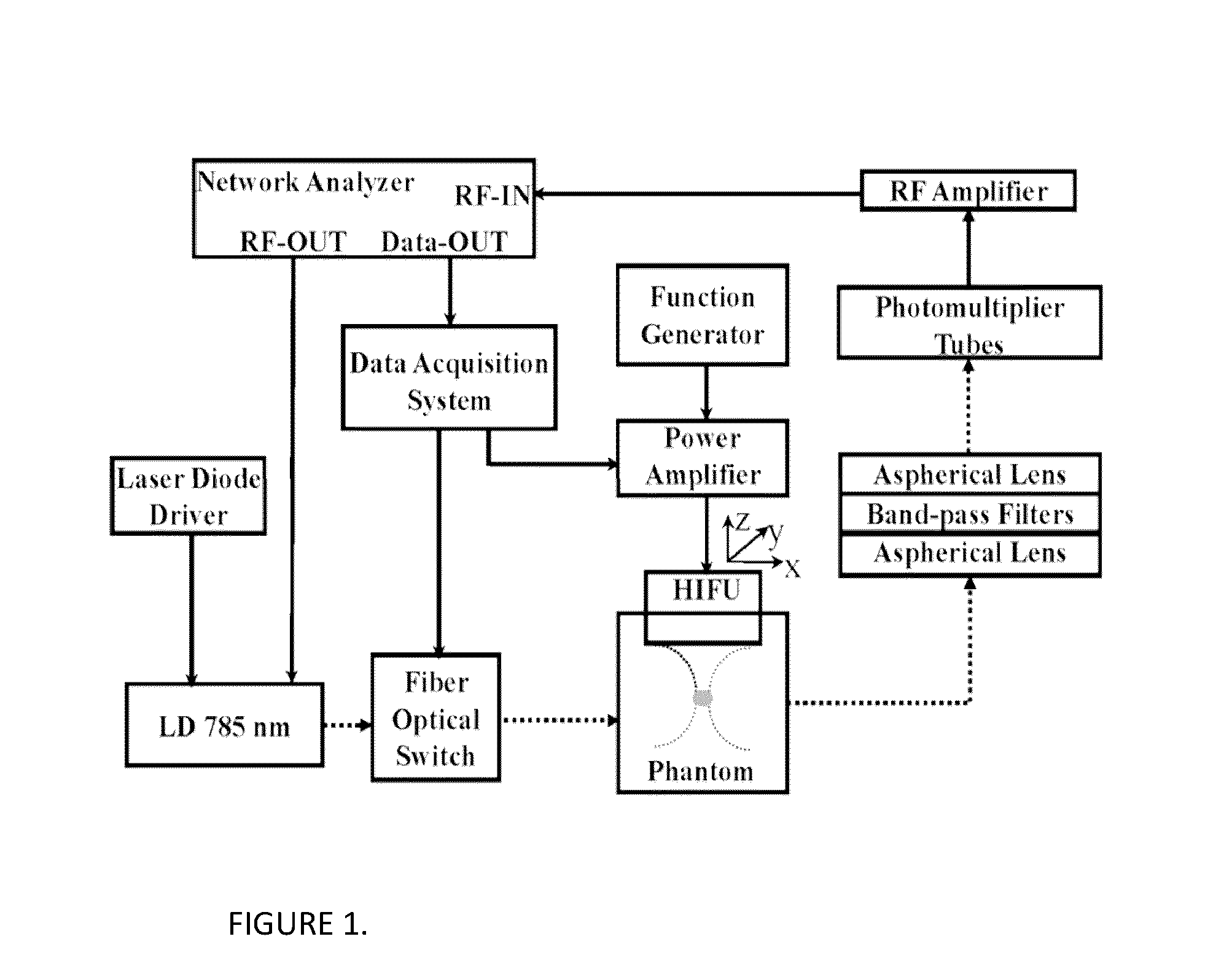
[0035]Experimental studies were carried out to demonstrate that the TM-FT could penetrate several centimeters thick scattering tissue, yet still at ultrasound resolution (sub-millimeter). The schematic diagram of the system is shown in FIG. 1. A 785 nm laser diode (80 mW, Thorlabs, Newton, N.J.) was used for fluorescence excitation. This laser wavelength was chosen due to high absorption of ICG, the fluorescence contrast agent used in this particular nanocapsule. Any wavelength can be used depending on the absorption spectrum of the particular fluorescent agent used in the nanocapsule. Near-infrared (NIR) wavelength range (600-1100 nm) would be especially suitable for in vivo imaging due to low absorption of tissue in this range. A network analyzer (Agilent Technologies, Palo Alto, Calif.) not only provided the RF modulation for the laser-diode but also measured the amplitude of the detected signal at the same time. A photomultiplier tube (PMT) (R7400U-20 Hamamatsu, Japan) was used ...


PUM


Abstract

Aspects of the disclosure relate to fluorescence imaging, and more particularly to the use of temperature modulation in a tissue site with a modulator such as high intensity focused ultrasound to modulate the emission signal emitted by temperature-sensitive optical fluorescence reporters.

Description

[0001]STATEMENT REGARDING FEDERALLY SPONSORED R&D[0002]The invention was made with government support under grants CA120175 and EB008716 from the National Institutes of Health. The government has certain rights in the invention.BACKGROUND OF THE INVENTION[0003]1. Field of the Invention[0004]Aspects disclosed herein relate to fluorescence based reporter imaging, and more particularly to the use of temperature modulation in a scattering medium with high intensity focused ultrasound or any other form of radiation to modulate the optical signal emitted by temperature-sensitive optical reporters.[0005]2. Description of the Related Art[0006]High scattering in biological tissues does not permit optical imaging of fluorescence in thick tissue with high resolution. As one of the optical imaging techniques, fluorescence tomography (FT) utilizes laser light to excite the fluorescence sources located deep in a medium. Once excited, these sources relax to their ground state in nanoseconds by emi...

Claims


Application Information

Patent Timeline
Patent Type & Authority Applications(United States)
IPC IPC(8): A61B5/00
CPCA61B5/0071A61B5/0097A61B5/0073
Inventor GULSEN, GULTEKINLIN, YUTING
Owner RGT UNIV OF CALIFORNIA
Learn More