Methods of forming a glass wiring board substrate

Inactive Publication Date: 2013-09-19
CORNING INC
View PDF4 Cites 15 Cited by
  • Summary
  • Abstract
  • Description
  • Claims
  • Application Information

AI Technical Summary

Benefits of technology

[0009]The glass material offers a low CTE well-matched to that of silicon. The forming process offers a dimensional reproducibility based on the use of non stick molds, desirably of graphite, the molds having a CTE close to the material to be formed. The forming process consists of pressing a glass sheet using one mold surface or two mold surfaces simultaneously, each mold surface presenting protrusions corresponding to the through-holes to be formed in the glass.
[0010]For embodiments of the method in which the through-holes are formed by pressing with a single mold, the holes may be blind holes after pressing, and may then be opened to form through-holes by back side lapping. Alternative

Problems solved by technology

Polymer CTE is generally undesirably high relative to silicon, and mechanical drilling becomes difficult at smaller hole and pitch sizes.
A remaining technical

Method used


Image

  • Methods of forming a glass wiring board substrate
  • Methods of forming a glass wiring board substrate
  • Methods of forming a glass wiring board substrate

Examples


examples

[0026]For Corning Code 0211 glass (available from Corning Incorporated of Corning, N.Y., USA and / or their distributors) a desirable graphite material may be EDM4 (available from Poco Graphite, Inc., Decatur, Tex., USA or their distributors) having a CTE of 78×10−7 / ° C. Mold surfaces comprising EDM4 were used to press Corning Code 0211 glass at 740° C. in a nitrogen atmosphere.

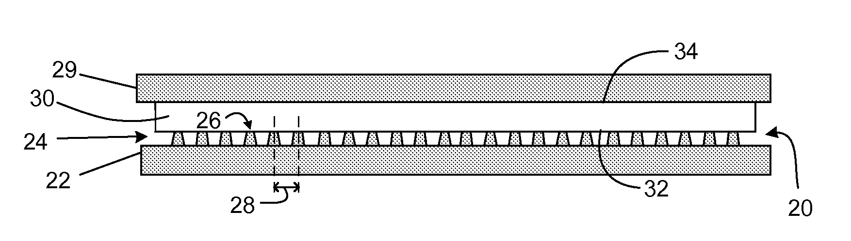
[0027]For actual production molds, diamond-tool machining is the preferred method for their formation. For the testing reported here, an EDM4 graphite mold was machined by wire EDM to produce 10 000 pins on 40×40 mm molding surface, the pins having a mean pitch 400 μm, a mean height of 230 μm, and a diameter at the bottom of the pins of 250 μm and 150 μm at the top. This mold was then used to press a sheet of Corning Code 0211 glass at 740° C. in a nitrogen atmosphere.

[0028]For back polishing, the molded glass was secured on a polishing support with adhesive wax melted at 70° C., then ground and polished to the...


PUM

PropertyMeasurementUnit
Lengthaaaaaaaaaa
Lengthaaaaaaaaaa
Moldableaaaaaaaaaa

Abstract

Disclosed is a method or process for forming a glass wiring board substrate for integrated circuit wiring boards, including providing a first molding surface (20) positioned on a first mold (22) having truncated conical pins (24) protruding therefrom, the pins (24) having a diameter at the top end (26) thereof of 150 micrometers or less, and a minimum pitch (28) of 400 micrometers or less, providing a glass sheet (30) having first and second surfaces (32,34) on opposite major sides thereof, pressing the first surface (32) of the glass sheet against the molding surface (20), heating the glass sheet (30) and the first molding surface (20) together to a temperature sufficient to soften a glass of which the glass sheet (30) is comprised, such that the pattern of the first molding (20) surface is replicated in the first surface (32) of the glass sheet (30), thereby producing a formed glass sheet (30′) having an array of holes (40) therein, cooling the formed glass sheet (30′) and the molding surface (20) together to a temperature below the softening point of said glass, and separating the formed glass sheet (30) from the molding surface (20). The forming may press the glass sheet using one mold surface or two mold surfaces simultaneously. For embodiments using a single mold, the holes may be blind holes after pressing, and may then be opened to form through-holes by back side lapping. Alternatively, the glass is pressed up to through-hole formation, avoiding the need of back side lapping.

Description

[0001]This application claims the benefit of priority under 35 USC §119 to U.S. Provisional Application Ser. No. 61 / 417,925 filed Nov. 30, 2010 the content of which is relied upon and incorporated herein by reference in its entirety.FIELD[0002]The present disclosure is related to package-integrated wiring board substrates particularly useful for CPU or GPU packaging, and particularly to methods for forming glass wiring board substrates.BACKGROUND AND SUMMARY[0003]Newer generations of high-performance integrated circuits such as central processing units (CPUs) and graphics processing units (GPUs) are getting larger and are being designed to operate over wider operating temperature ranges than past generations. Larger sizes and larger operating temperature ranges cause a need for low coefficient of thermal expansion (low CTE) materials with CTE relatively close to silicon for use as wiring board substrates within the packaging of newer generation integrated circuits.[0004]In typical p...

Claims


Application Information

Patent Timeline
IPC IPC(8): C03B23/26
CPCC03B23/26C03B23/02H01L2224/16225H01L2224/73253H01L2924/15174H01L2924/15311H01L2924/16152H01L2924/19106
Inventor DANNOUX, THIERRY LUC ALAIN
Owner CORNING INC
Why Eureka
Try Eureka