Electrolysis cell for generating ozone for treating a liquid

Inactive Publication Date: 2013-09-19
BRITA GMBH
View PDF4 Cites 11 Cited by
  • Summary
  • Abstract
  • Description
  • Claims
  • Application Information

AI Technical Summary

Benefits of technology

The patent text describes a method for generating ozone using a specific type of electrolyte. This method has several advantages, including a higher ozone yield, the ability to use mains water, and reduced formation of disinfection by-products. The main technical effect is the increased efficiency and suitability for generating ozone from liquids other than ultrapure water.

Problems solved by technology

The outlet pieces in particular give rise to the risk of retrograde contamination of the drinking water by undesirable and frequently health-endangering germs such as bacteria, protists, fungi, parasites, viroids, viruses, algae or prions, which are present in the conduit systems of the liquid dispensing or drinking water dispensing apparatuses and can become settled there.
However, a risk is posed not only by retrograde contamination but also by the conduit system itself, in which health-endangering germs can likewise be present and spread.
The irradiation of the liquid with UV light has the disadvantage that the germs are inactivated only in the radiation region of the UV lamp, so that only some of the germs are inactivated and the germs which have not been inactivated can spread further in other places in the apparatus.
The use of a purifying agent which can be transported through the entire apparatus has the disadvantage that it is generally not drinkable and therefore has to be collected and completely removed from the apparatus before the apparatus can be used again to dispense drinking water.
This is disadvantageous in particular because the apparatus cannot fulfil its intended purpose for a certain time.
A gas separator is required since residual gases which can be toxic to the user have to be destroyed.
The electrodes used consist of lead oxide and, especially in the case of discontinuous operation of the apparatus, have the disadvantage that they release lead constituents into the liquid to be treated, which is unacceptable in terms of the health of the user.
However, the electrolysis cells disclosed therein serve the treatment of gases, so that application to the present case is not possible.
In particular, in the treatment of liquids the problem occurs that the maximum volume stream which can be passed through the electrolysis cell represents a limiting factor due to the incompressibility of liquids.
To guarantee the stability of the electrolysis cell, the solid-state electrolyte has to be provided in a relatively complicated shape, which gives rise to a high volume requirement.
This is a disadvantage for storage, simple transport and replacement of a used electrolysis cell.
However, the known electrolysis cell functions only with ultrapure water.

Method used


Image

  • Electrolysis cell for generating ozone for treating a liquid
  • Electrolysis cell for generating ozone for treating a liquid
  • Electrolysis cell for generating ozone for treating a liquid

Examples


Embodiment Construction

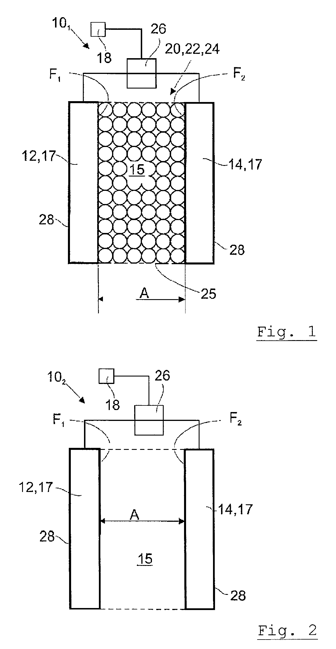
[0087]The electrolysis cell 101 depicted in FIG. 1 comprises a first electrode 12 having a first surface F1 and a second electrode 14 having a second surface F2, which face one another and are arranged at a distance A to one another. The electrodes 12,14 each have a support core 17 to which a diamond coating 28 has been applied. To be able to make the diamond coating 28 electrically conductive, it is doped. Furthermore, the electrolysis cell 10 comprises a measurement device 26 to determine the cell resistance and to activate the electrolysis cell 10 in dependence on a determinable event. The measurement device 26 is connected to a power supply 18 for controlling the voltage as a function of the measured cell resistance.

[0088]The two electrodes 12,14 form a free space 15 through which liquid, for example water, can flow, and which is filled with a particulate solid-state electrolyte 20, which may be an ion exchanger 22 or a zeolite 24 that has been made acidic or a polymer 24. As po...


PUM

PropertyMeasurementUnit
Electrical conductivityaaaaaaaaaa
Polarityaaaaaaaaaa
Concentrationaaaaaaaaaa

Abstract

An electrolysis cell for generating oxidizing agents, in particular ozone, for treating a liquid comprises a first electrode and a second electrode. The first and the second electrodes are spaced apart from one another by a distance (A). A particulate solid electrolyte is arranged between the first and the second electrodes and can have the liquid flowing through it. The solid electrolyte is arranged in a free space bounded by the first and the second electrodes.

Description

FIELD OF THE INVENTION[0001]The present invention relates to an electrolysis cell for generating oxidants, in particular ozone, for treating a liquid, comprising a first electrode and a second electrode, wherein the first electrode and the second electrode are arranged at a distance to one another and wherein a particulate solid-state electrolyte is arranged between the first electrode and the second electrode, through which the liquid can flow.[0002]The invention further concerns an apparatus for treating a liquid, comprising an inlet for introducing liquid into the apparatus, an outlet piece for discharging the treated liquid from the apparatus, a treatment region which can be supplied with water for treating the water.[0003]In addition, the invention relates to a method of generating ozone for the treatment of a liquid.BACKGROUND OF THE INVENTION[0004]Liquid dispensing or drinking water dispensing apparatuses such as for example coolers, chillers, water bars or vending machines, ...

Claims


Application Information

Patent Timeline
IPC IPC(8): C02F1/78C25B1/13
CPCC02F1/46114C02F1/4672C02F1/78C02F2001/46138C02F2201/4613C02F2201/46135C25B1/13C02F2209/04C02F2209/05C02F2209/23C02F2301/043C02F2307/10C02F2201/46195
Inventor CONRADT, BERTHOLDWEIDNER, PETERKEMMER, RON
Owner BRITA GMBH
Why Eureka
Try Eureka