
Implantable materials for bone repair

Active Publication Date: 2013-09-19
CERAPEDICS
View PDF4 Cites 46 Cited by
  • Summary
  • Abstract
  • Description
  • Claims
  • Application Information

AI Technical Summary

Benefits of technology

The invention is about a new type of bone repair material that can be used to treat bone defects. The material is made up of ceramic particles mixed with flexible fiber reinforcement. The resulting material is easy to manipulate by a physician during an implantation procedure without tearing or puncturing. When the material is formed into a pliable implant, it has a specific strength and flexibility. The material also has the ability to reduce migration of the ceramic particles and can be aggressively manipulated without tearing or puncturing. The pliable implant can also be formed with a specific force ratio and yield stress ratio. Overall, the invention provides a new and effective way to treat bone defects.

Problems solved by technology

Sometimes, however, this approach is insufficient because the patient has lost some of the bone.
This can happen in certain kinds of trauma where the bone is so badly shattered that it cannot feasibly be pieced together.
More often, it happens as a result of disease that destroys bone mass or as the result of osseous surgery in which destruction of bone mass is unavoidable.
Completely resorbed material eliminates the possibility for a stress riser that can occur when foreign matter remains in the skeleton, potentially giving rise to a fracture in the future.
This means greater cost, and increased risk of infection and morbidity for a patient that is already seriously ill or injured.
Also, this approach can require a great deal of time and surgical skill as the surgeon removes the donated material from the donation site, shapes and fits it to the primary site, and then repairs both sites.
Finally, there is quite obviously a limit to the amount of bone in the patient's body available to be sacrificed as donor material.
A key limitation is whether the function of the treatment requires that the material be resorbed by natural bodily actions or remain in place as permanent supporting structures.
The ceramic particulates, unformulated, are available as dry granules and generally lack sufficient cohesiveness and adhesion for filling an osseous defect.
However, too fast a degradation rate is not preferred since cellular and vascular infiltration cannot develop.
Too slow of a resorption rate also interferes with cellular migration, vascular penetration and bone formation.

Method used


Image

  • Implantable materials for bone repair
  • Implantable materials for bone repair
  • Implantable materials for bone repair

Examples


example 1

Preparation of Fiber-Reinforced Implantable Materials

[0068]A fiber reinforced putty and fiber reinforced Flex (lyophilized putty) were prepared using methods analogous to those described in PCT Publication No. WO2007070681.

[0069]Preparation of Putty

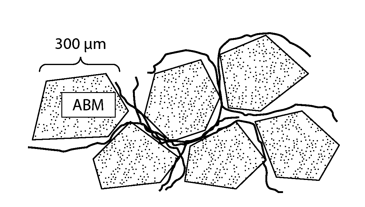
[0070]A putty material containing about 51.9% (w / w) anorganic bone mineral particles (ABM, a natural microporous, xenogenic bone material also known as OsteoGraf®-N 300); about 1.5% (w / w) sodium carboxymethyl cellulose; about 6.98% (w / w) glycerol; and about 39.57% (w / w) water was prepared mixing the water, glycerol, and sodium carboxymethyl cellulose to form a hydrogel, and mixing the ABM particles with the hydrogel to form a putty. The hydrogel / putty is optionally subjected to a vacuum to remove any air bubbles formed during mixing. The ABM particles optionally include P-15 peptide (see U.S. Pat. No. 5,635,482) bound to their surface (sold as PEPGEN P-15® by Dentsply Tulsa Dental Specialties).

[0071]Preparation of Fiber-Reinforced Putty

[0...

example 2

The Modified Ball Punch Deformation Test

[0076]The fiber reinforced Flex can improve ease of handling and implantation by a surgeon in comparison to fiberless formulations. The fiber reinforced materials can also reduce particle migration post implantation.

[0077]A tensile test, which is the standard mechanical test for current Flex product, cannot properly test the material in a real-world scenario since the product is rarely pulled apart. Rather, during implantation of the lyophilized formulations, manual pressure is applied to strips of Flex in a puncturing motion, not pulling. To ascertain the performance of the product under realistic surgical conditions, an ideal test would also be performed on both dry and wetted (using various techniques and fluids) Flex samples.

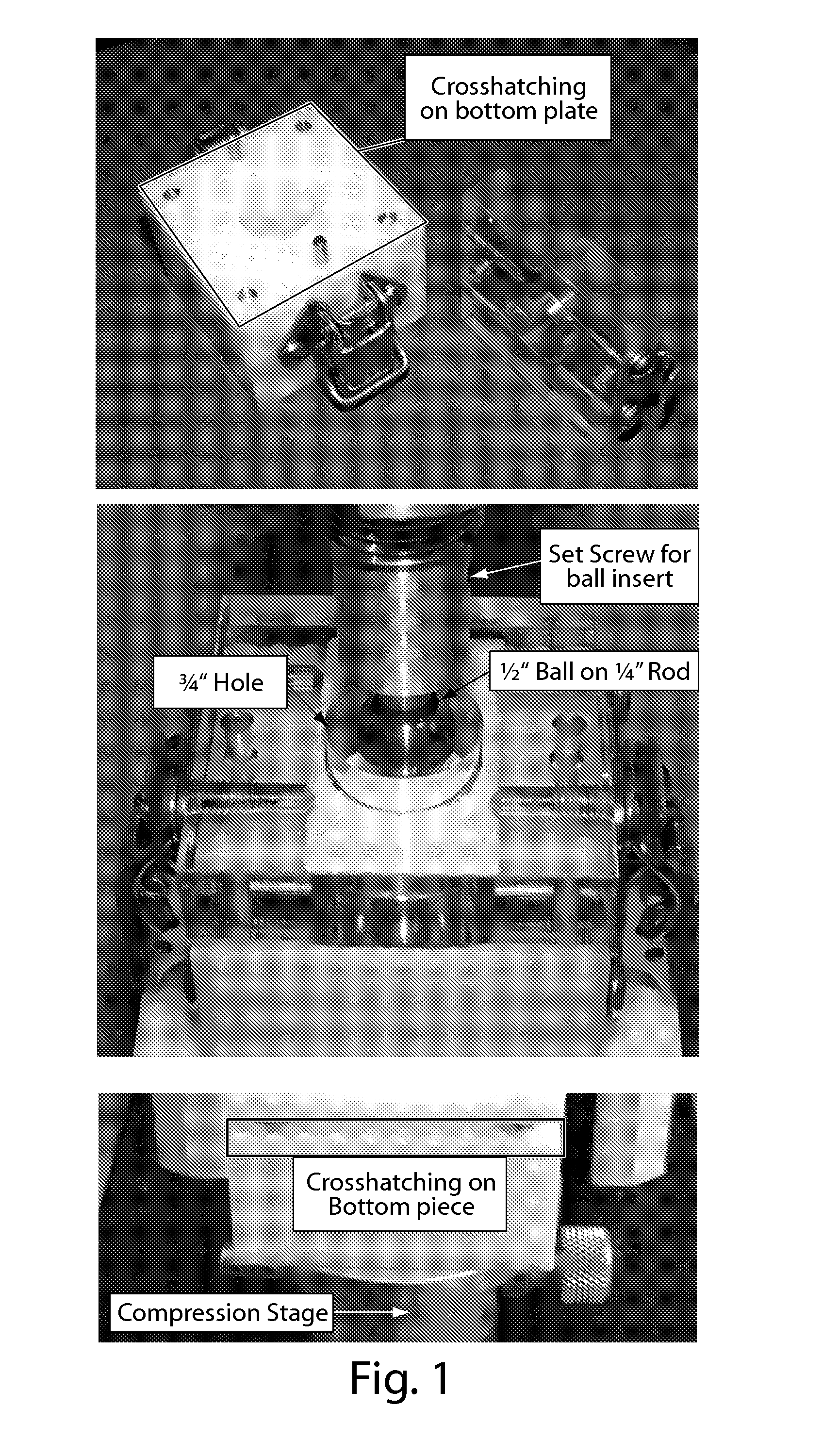
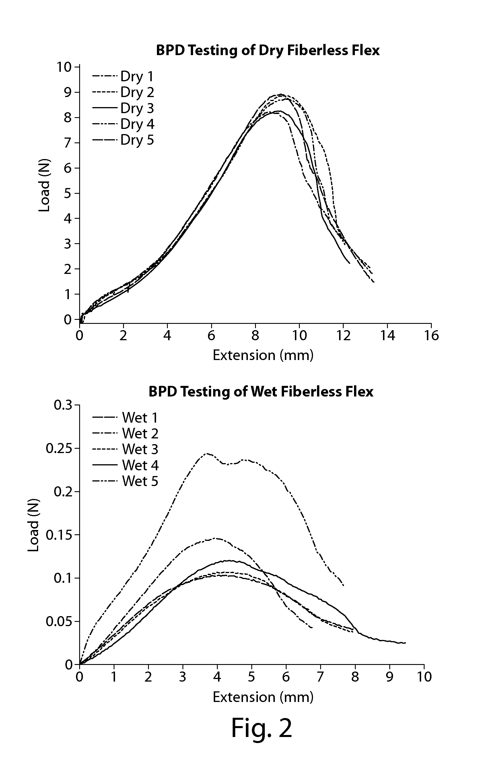
[0078]To assess whether a fiber reinforced Flex can better withstand manual puncturing motion, a new testing method, the Modified Ball Punch Deformation Test (BPD test), was developed. The BPD test mimics real-world ha...

example 3

Effect of Silk Fiber Length and Concentration on Mechanical Properties for Fiber Reinforced Flex

[0082]The purpose of the following study was to understand the effect of silk fiber length and concentration on mechanical properties for silk fiber reinforced Flex (SFR Flex) samples.

[0083]SFR Flex samples were prepared using the methods described in Example 1. The fibers used for this study were roving silk fiber (textile grade) cut to ½″, ⅜″ and ¼″ lengths. The samples were subjected to BPD testing as described in Example 2. The results are tabulated below in Table 2.

TABLE 2FiberFiberLoad atLengthPercentageTestingFailure(in)(%)Environment(N)NA0Dry13.53Wet0.352½1.0Dry55.85Wet20.7940.5Dry42.13Wet6.2940.25Dry32.2Wet2.395⅜1.0Dry63.09Wet26.9810.5Dry39.83Wet10.4970.25Dry26.07Wet5.435¼1.0Dry50.49Wet9.4570.5Dry22.12Wet3.6580.25Dry21.43Wet2.753

[0084]Results and Discussion:

[0085]A steady decrease in LAF can be observed as fiber content decreases, the lowest LAF values generally being observed in...


PUM

PropertyMeasurementUnit
Lengthaaaaaaaaaa
Lengthaaaaaaaaaa
Fractionaaaaaaaaaa

Abstract

The invention features fiber reinforced bone repair putties and fiber reinforced pliable lyophilized implants which are useful for the treatment of bone defects. The putties and lyophilized implants include ceramic particles. The formulations of the invention can exhibit reduced migration of the ceramic particles, and are mechanically strengthened so the materials can be aggressively manipulated by a physician during an implantation procedure without tearing or puncturing.

Description

CROSS REFERENCE TO RELATED APPLICATIONS[0001]This application claims benefit from U.S. provisional application Ser. No. 61 / 579,806, filed Dec. 23, 2011, and incorporated herein by reference.BACKGROUND OF THE INVENTION[0002]The invention relates to the field of bone void fillers, and their use for the treatment of orthopedic conditions.[0003]Physicians are sometimes called upon to repair bone that has been damaged by disease, trauma, osseous surgery or other causes, or to cause bone material to grow where there has been no bone before, such as during a spine fusion procedure. As an outcome of that procedure, it is desirable for two or more vertebral bodies to be maintained in a specific orientation. This can be accomplished by growing a column or bridge of rigid bone between the vertebral bodies. This maintains them in a fixed position relative to each other. The repair of long bone fractures can often be accomplished merely by relocating disrupted bone elements into natural proximit...

Claims


Application Information

Patent Timeline
IPC IPC(8): A61L27/58A61L27/42
CPCA61L27/427A61L27/58A61L27/12A61K38/39A61L27/46A61L27/52A61L2430/02A61L27/3608A61P19/00A61P19/08
Inventor BENEDICT, JAMES J.HANNIGAN, NOLAN CHASEDAVIS, KATHERINE SUZANNEYOUNG, WHITNEY TERESE
Owner CERAPEDICS
Learn More