
Optical film

a technology film, applied in the field of optical retardation film, can solve the problems of oblique viewing angle contrast ratio drop, polarizers becoming uncrossed, low contrast ratio at wide viewing angle along the bisector of crossed polarizers

Inactive Publication Date: 2013-09-26
CRYSOPTIX
View PDF4 Cites 6 Cited by
  • Summary
  • Abstract
  • Description
  • Claims
  • Application Information

AI Technical Summary

Benefits of technology

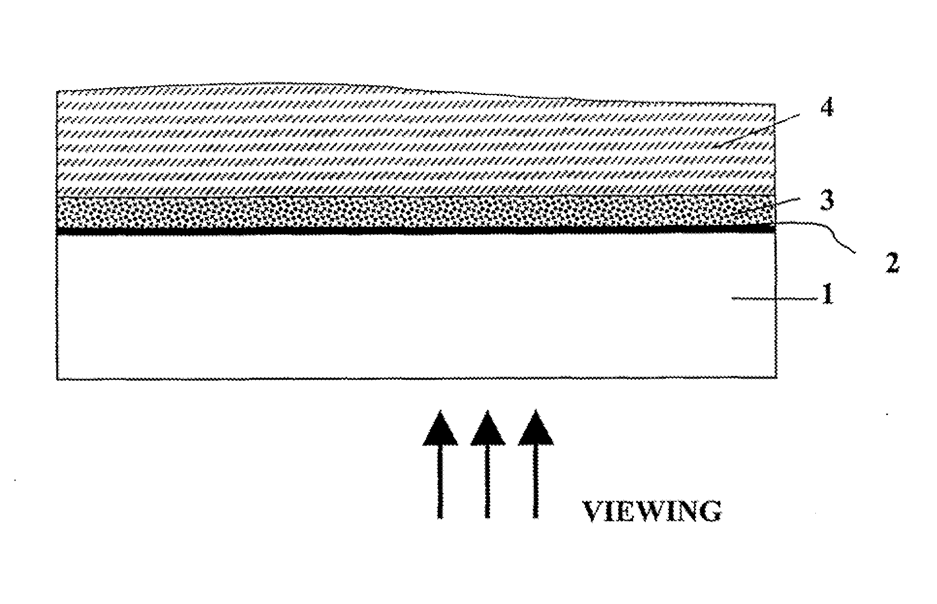
The present invention provides an optical film with a layer of organic rigid rod-like macromolecules on the front surface of the film substrate. This layer acts as a negative C-type or Ac-type plate, which is transparent to electromagnetic radiation in the visible spectral range. The film has a unique structure and can be used as an optical retardation layer in various applications such as displays, sensors, and surveillance systems. The layer of organic rigid rod-like macromolecules can be dissolved in aqueous solvent and countered with different ions to achieve desired optical properties.

Problems solved by technology

Nowadays there are still some disadvantages of LCD technology which impact quality of liquid crystal displays and still make feasible competitive technologies as for example plasma display panel (PDP).
One of disadvantages is a decrease of contrast ratio at oblique viewing angles.
However, at oblique angles an angle between projections of their axes deviates from 90°, and the polarizers become uncrossed.
This results in a low contrast ratio at wide viewing angle along the bisector of crossed polarizers.
Moreover, the light leakage becomes worse because of the liquid crystal cell placed between crossed polarizers.
However, their disadvantage is a low value of birefringence.
However, the described method has a technological drawback.

Method used


Image

  • Optical film
  • Optical film
  • Optical film

Examples


example 1

[0041]The example describes synthesis of 2,2′-disulfo-4,4′-benzidine terephthalamide-isophthalamide copolymer cesium salt.

[0042]The same method of synthesis can be used for preparation of the copolymers of different molar ratio.

[0043]4.098 g (0.012 mol) of 4,4′-diaminobiphenyl-2,2′-disulfonic acid was mixed with 4.02 g (0.024 mol) of cesium hydroxide monohydrate in water (150 ml) in a 1 L beaker and stirred until the solid was completely dissolved. 3.91 g (0.012 mol) of sodium carbonate was added to the solution and stirred at room temperature until dissolved. Then toluene (25 ml) was added. Upon stirring the obtained solution at 7000 rpm, a solution of 2.41 g (0.012 mol) of terephthaloyl chloride (TPC) and 2.41 g (0.012 mol) of isophthaloyl chloride (IPC) in toluene (25 ml) were added. The resulting mixture thickened in about 3 minutes. The stirrer was stopped, 150 ml of ethanol was added, and the thickened mixture was crushed with the stirrer to form slurry suitable for filtration...

example 2

[0044]The example describes preparation of a solid optical retardation layer of negative C-type with 2,2′-disulfo-4,4′-benzidine terephthalamide-isophthalamide copolymer (terephthalamide / isophthalamide molar ratio 50:50) prepared as described in Example 1.

[0045]2 g of poly(2,2′-disulfo-4,4′-benzidine terephthalamide-isophthalamide copolymer) cesium salt was dissolved in 100 g of de-ionized water (conductivity ˜5 μSm / cm). The suspension was mixed with a magnet stirrer. After dissolving, the solution was filtered with the hydrophilic filter with a 45 μm pore size and evaporated to the viscous isotropic solution of the concentration of solids of about 6%.

[0046]Fisher brand microscope glass slides were prepared for coating by soaking in a 10% NaOH solution for 30 min, rinsing with deionized water, and drying in airflow with the compressor. At temperature of 22° C. and relative humidity of 55% the obtained LLC solution was applied onto the glass panel surface with a Gardner® wired stainl...

example 3

[0047]The example describes preparation of a solid optical retardation layer of Ac-plate type with 2,2′-disulfo-4,4′-benzidine terephthalamide-isophthalamide copolymer (terephthalamide / isophthalamide molar ratio 92:8) prepared as described in Example 1.

[0048]2 g of poly(2,2′-disulfo-4,4′-benzidine terephthalamide-isophthalamide copolymer) cesium salt produced as described in Example 1 was dissolved in 100 g of de-ionized water (conductivity ˜5 μSm / cm), and the obtained suspension was mixed with a magnet stirrer. After dissolving, the solution was filtered with the hydrophilic filter of a 45 μm pore size and evaporated to form viscous birefringent solution of concentration of solids of approximately 6%.

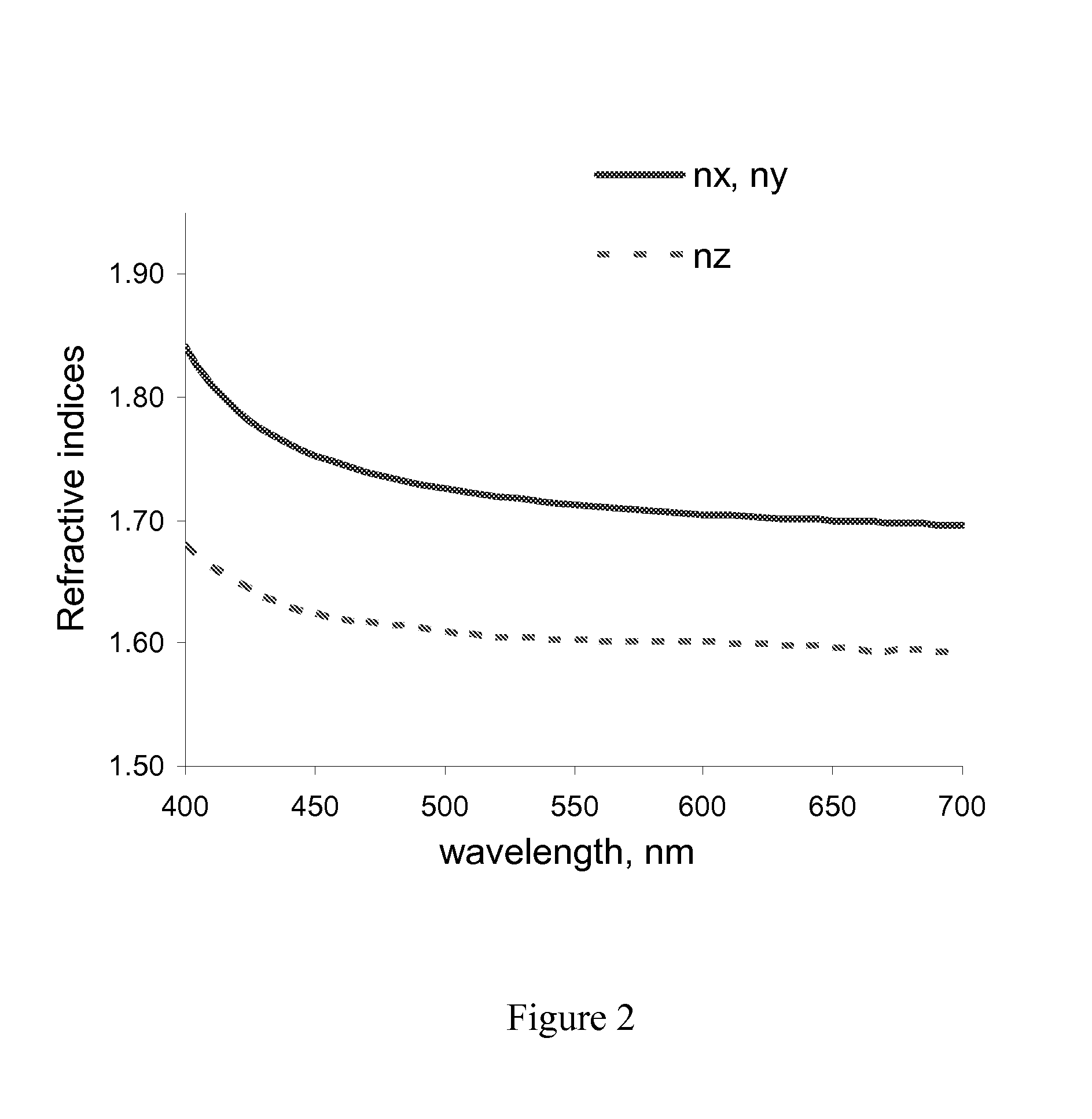
[0049]The coatings were produced and optically characterized as described in Example 2 with the Mayer rod #8 used for coating. The refractive index spectral dependencies are presented in FIG. 3. The obtained solid optical retardation layer was characterized by thickness of approximatel...


PUM

PropertyMeasurementUnit
thickness retardation Rthaaaaaaaaaa
sizeaaaaaaaaaa
angleaaaaaaaaaa

Abstract

The present invention relates generally to optical retardation films. The invention may be used as optical element in liquid crystal display (LCD) devices, particularly as phase-shifting component of LCDs of both reflection and transmission type, and in ant other field of science and technology where optical retardation films are applied such as architecture, automobile industry, decoration arts. The present invention provides an optical film comprising a substrate having front and rear surfaces, and at least one solid optical retardation layer on the front surface of the substrate. The solid optical retardation layer comprises organic rigid rod-like macromolecules based on 2,2′-disulfo-4,4′-benzidine terephthalamide-isophthalamide copolymer or its salt of the general structural formula I. The solid optical retardation layer is a negative C-type or Ac-type plate substantially transparent to electromagnetic radiation in the visible spectral range.

Description

CROSS REFERENCE TO RELATED APPLICATIONS[0001]This application is related to U.S. patent application Ser. No. 12 / 628,398 filed on Dec. 1, 2009, entitled “Organic Polymer Compound, Optical Film and Method”, the entire disclosure of which is incorporated by reference herein.FIELD OF THE INVENTION[0002]The present invention relates to optical retardation films. The invention may be used as optical element in liquid crystal display (LCD) devices, particularly as phase-shifting component of LCDs of both reflection and transmission type, and in any other field of science and technology where optical retardation films are applied.BACKGROUND OF THE INVENTION[0003]The liquid crystal display (LCD) technology has made a remarkable progress in the past years. Cellular phones, laptops, monitors, TV sets and even public displays based on LCD panels are presented on the market. LCD market is expected to keep growing in the near future and it sets new tasks for researchers and manufacturers. Among t...

Claims


Application Information

Patent Timeline
Patent Type & Authority Applications(United States)
IPC IPC(8): G02B1/04G02B1/10
CPCG02B1/04Y10T428/24521C09K19/04C09K19/22G02F1/133634G02F2001/133635G02F2201/38G02F2201/50G02F2202/022G02F2202/28G02F2413/11G02F2413/12Y10T428/24364Y10T428/24942Y10T428/2848G02B1/10Y10T428/31757Y10T428/31736Y10T428/31725Y10T428/31507Y10T428/31721Y10T428/3175Y10T428/31623G02F1/133635G02B1/11
Inventor LAZAREV, ALEXANDER
Owner CRYSOPTIX
Learn More