
Fired heater and method of using the same

a technology of fire-heating heater and combustion chamber, which is applied in the direction of lighting and heating equipment, combustion types, solid fuel combustion, etc., can solve the problems of indirect waste of fuel, increase production costs, and negative influence on the environment, so as to reduce or eliminate the fluctuation of the flow rate of the flue gas or the temperature of the discharged flue gas

Active Publication Date: 2013-10-03
CHINA PETROCHEMICAL CORP +1
View PDF11 Cites 3 Cited by
  • Summary
  • Abstract
  • Description
  • Claims
  • Application Information

AI Technical Summary

Benefits of technology

The present invention is a fired heater with improved thermal efficiency that can recover the heat from the flue gas. It has alternating heat exchange chambers that can recover heat from the flue gas at different stages, which prevents corrosion and lowers the temperature of the flue gas. The gas mixing tank ensures a steady air supply without flameout. Blowers reduce fluctuations in the air and flue gas flow rates, ensuring stable temperature and pressure in the fired heater. The fired heater is small, long-life, and easy to use.

Problems solved by technology

Compared with a condensing boiler, a fired heater discharges flue gas containing a large amount of unutilized sensible heat and latent heat, causing an indirect waste of fuel, increasing the production cost and exerting a negative influence on the environment.
In discharging the flue gas, the water vapor condenses and dissolves the SO2 to produce sulfurous acid, sulfuric acid, etc, which will corrode the entire exhaust equipment of the fired heater and pollute the environment as well.
Moreover, because of the volume effect of the heat exchange chamber, the residual flue gas therein would re-enter into the fired heater and cause a flameout therein due to a lack of oxygen.
These problems severely limit the application of the high frequency commutation ceramic regenerative heat exchanger in the field of the fired heater.

Method used


Image

  • Fired heater and method of using the same
  • Fired heater and method of using the same
  • Fired heater and method of using the same

Examples


Embodiment Construction

[0030]The present invention will be further described with reference to the accompanying drawings.

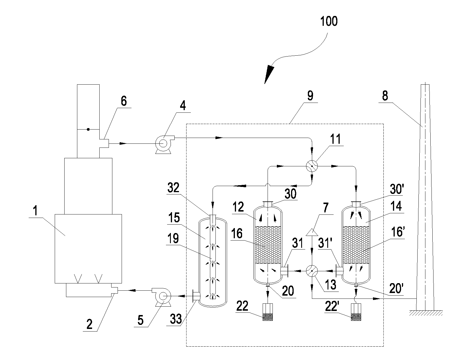
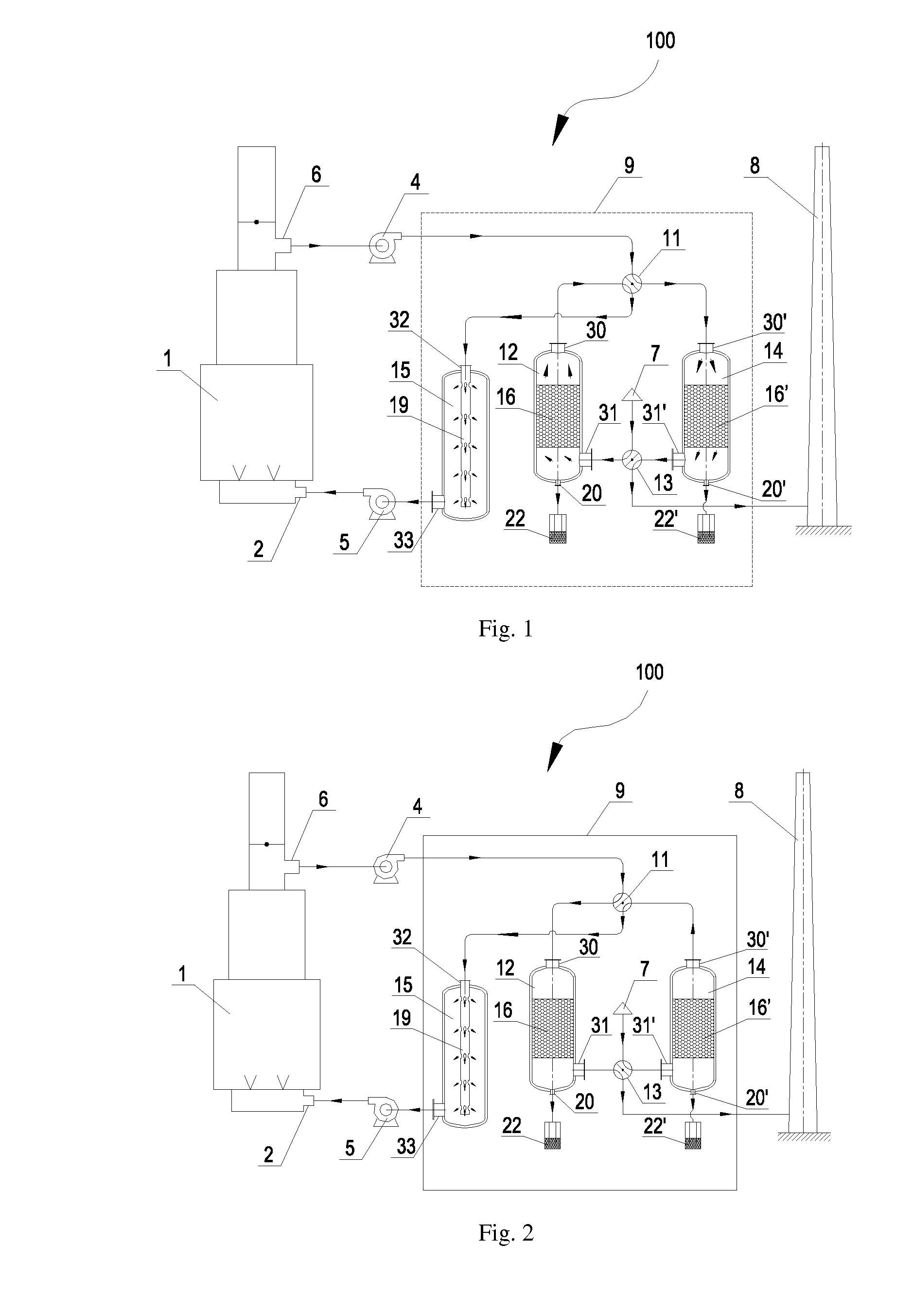
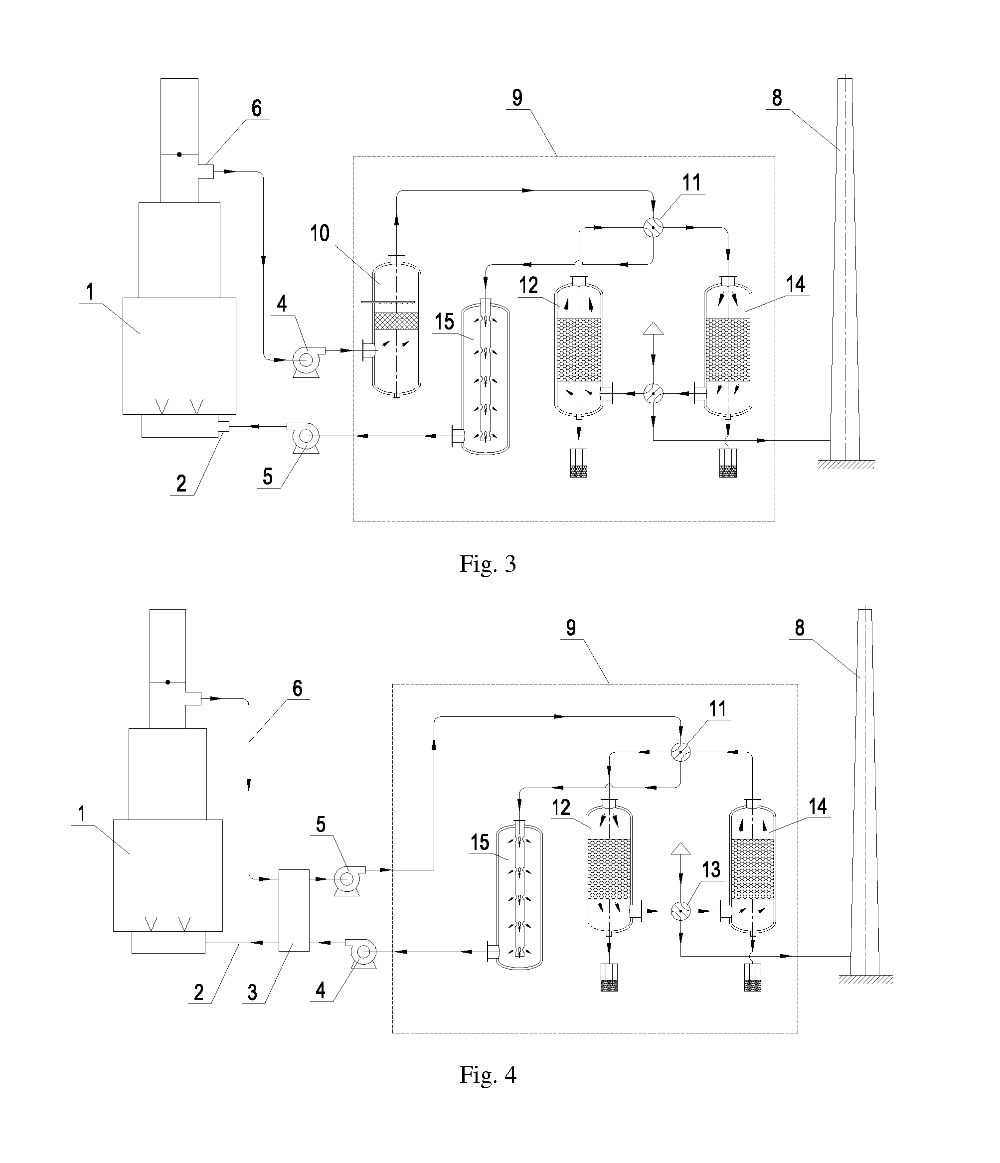
[0031]FIG. 1 schematically shows the fired heater 100 according to the present invention, including a fired heater body 1 and a flue gas waste heat recovery system 9 (as shown in the dashed box in FIG. 1) communicated with the fired heater body 1. The flue gas waste heat recovery system 9 is used to recover the heat of the flue gas coming from the fired heater body 1, and then use the same to heat the air supplied to the fired heater body 1, such that the thermal efficiency of the fired heater 100 is improved. To further improve the thermal efficiency of the fired heater 100, a heat exchanger 3 can be provided between the fired heater body 1 and the flue gas waste heat recovery system 9. As shown in FIG. 4, the flue gas coming from the fired heater body 1 and the air supplied therein flow through the heat exchanger 3 in countercurrent or crossflow to achieve the heat exchange between th...


PUM


Abstract

A fired heater includes a fired heater body with an air inlet and a flue gas outlet, and a flue gas waste heat recovery system communicated with the fired heater body and including at least two heat exchange chambers. A first port of each of the heat exchange chambers can be communicated with the flue gas outlet or the air inlet, and a second port of each of the heat exchange chambers can be communicated with the outside air or a fume extractor. When the first port of at least one heat exchanger chamber is communicated with the flue gas outlet and the second port thereof is communicated with the fume extractor, the first port of at least another heat exchange chamber is communicated with the air inlet and the second port thereof is communicated with the outside air.

Description

TECHNICAL FIELD[0001]The present invention relates to an industrial heating apparatus, particularly to a fired heater. The present invention also relates to a method of using the fired heater.TECHNICAL BACKGROUND[0002]A fired heater is a widely used process furnace in the fields of petroleum, petrochemistry, natural gas and metallurgy. The fired heater is gas or oil-fueled, and the heat carrier materials in the furnace pipe are heated directly by the flame to meet the temperature requirement for downstream equipments.[0003]Currently, the exhaust gas temperature of a fired heater is generally high, normally within the range of 130˜180° C., such that the thermal efficiency of the fuel is usually between 88% and 92%. Compared with a condensing boiler, a fired heater discharges flue gas containing a large amount of unutilized sensible heat and latent heat, causing an indirect waste of fuel, increasing the production cost and exerting a negative influence on the environment. Additionally...

Claims


Application Information

Patent Timeline
Patent Type & Authority Applications(United States)
IPC IPC(8): F23L15/00F23J15/02F23C9/00
CPCF23L15/00F23J15/022F23C9/00Y02E20/34
Inventor WANG, DERUIYANG, LIRANZHANG, TIEFENG
Owner CHINA PETROCHEMICAL CORP
Learn More