Eureka AIR delivers breakthrough ideas for toughest innovation challenges, trusted by R&D personnel around the world.

Climate-control device for a vehicle, and method for regulating a climate in a passenger compartment of a vehicle

a technology for climate control and vehicles, which is applied in the direction of separation processes, lighting and heating apparatus, transportation and packaging, etc. it can solve the problems of consuming additional energy, providing heating or cooling capacity, and shortening the maximum possible range by up to 50%. , to achieve the effect of improving the thermal coupling of the adsorbent, improving the efficiency of the transfer of heat output, and efficient storage of the working medium

Inactive Publication Date: 2013-10-31
ROBERT BOSCH GMBH
View PDF8 Cites 7 Cited by
  • Summary
  • Abstract
  • Description
  • Claims
  • Application Information

AI Technical Summary

Benefits of technology

The patent describes a system for conditioning the air in a vehicle by using a gas mixture and a thermal energy store. This results in a more energy efficient system as less external air is needed, saving energy and reducing fuel consumption in vehicles with combustion engines. The system also uses an adsorption refrigeration unit to cool the air, resulting in a higher performance rating. The system combines the benefits of conditioning the air and energy storage to provide a more energy efficient and cost-effective solution for vehicles.

Problems solved by technology

However, the disadvantage of the known devices is that they can only provide a heating or cooling capacity.
However, this fresh air must be cooled or heated in an involved process, depending on temperature, and this consumes additional energy.
Particularly in the case of electric vehicles, this measure shortens a maximum possible range by up to 50% owing to the additional power consumption.
In a vehicle with an internal combustion engine, fuel consumption rises due to this measure.

Method used


Image

  • Climate-control device for a vehicle, and method for regulating a climate in a passenger compartment of a vehicle
  • Climate-control device for a vehicle, and method for regulating a climate in a passenger compartment of a vehicle
  • Climate-control device for a vehicle, and method for regulating a climate in a passenger compartment of a vehicle

Examples


Embodiment Construction

[0035]In the text which follows, identical reference signs are used for identical features.

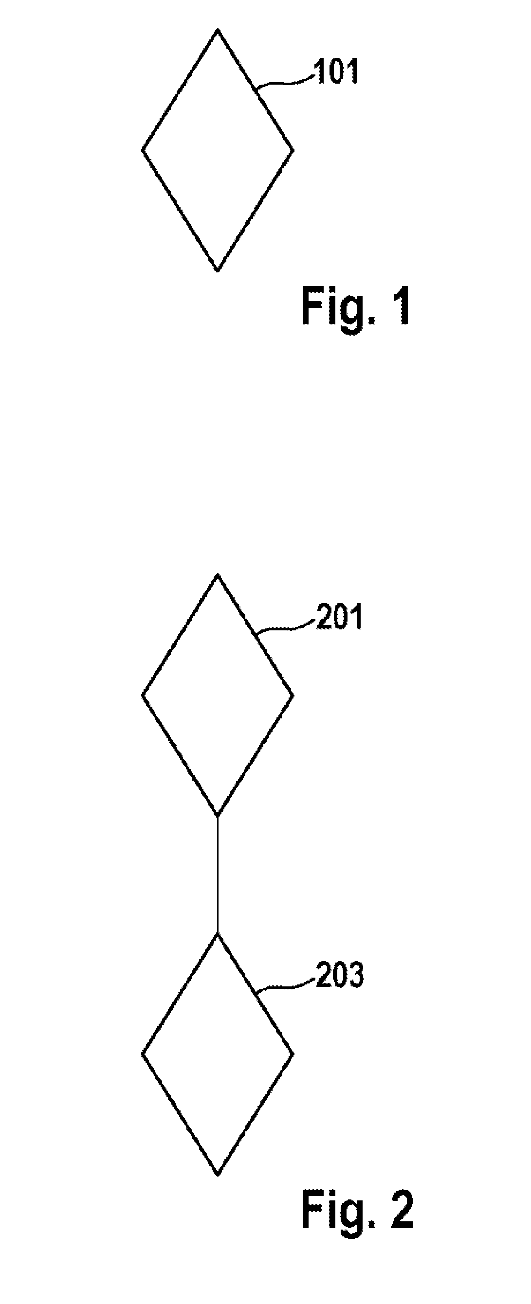
[0036]FIG. 1 shows one embodiment of a method for regulating a climate in a passenger compartment of a vehicle. In a step 101, a gas mixture situated in the passenger compartment is conditioned. The gas mixture is preferably air.

[0037]FIG. 2 shows another flow diagram of a method for regulating a climate in a passenger compartment of a vehicle. In a step 201, carbon dioxide is filtered out of the gas mixture. This filtering is preferably accomplished by means of an activated carbon filter and / or a molecular sieve. A molecular sieve preferably comprises a gas separation membrane. In this case, the gas mixture is preferably passed through the activated carbon filter or the molecular sieve. Regeneration of the activated carbon filter can preferably be accomplished by means of heating, in particular by means of electric heating. For an electric vehicle, regeneration preferably takes place during a...


PUM

PropertyMeasurementUnit
Energyaaaaaaaaaa

Abstract

The invention relates to a climate-control device (501) for a vehicle, having a thermal energy store (1105), wherein a gas recycler (1301) is formed for conditioning a gas mixture which is situated in a passenger compartment (1103) of the vehicle (1101). Furthermore, the invention relates to a method for regulating a climate in a passenger compartment (1103) of a vehicle (1101).

Description

BACKGROUND OF THE INVENTION[0001]The invention relates to a climate-control device for a vehicle. The invention furthermore relates to a method for regulating a climate in a passenger compartment of a vehicle.[0002]Adsorption heat exchangers for mobile applications in passenger compartment heating and cooling are known per se. Thus, for example, patent EP 1 809 499 B1 describes an adsorption heat pump for climate control in a motor vehicle.[0003]However, the disadvantage of the known devices is that they can only provide a heating or cooling capacity. In a recirculated air mode, that is to say when no fresh air is fed to a space to be cooled or heated, e.g. a passenger compartment, the air quality in the space, e.g. the passenger compartment, decreases as the time duration increases. In particular, a carbon dioxide content of the air increases while, at the same time, an oxygen content of the air falls. Moreover, a moisture content also increases due to respiration and transpiration...

Claims


Application Information

Patent Timeline
IPC IPC(8): B60H1/32B60H1/02B60H3/06B60H1/00
CPCB60H1/3201B60H1/00328B60H1/02B60H3/06B01D53/0438B01D2253/102B01D2253/106B01D2253/108B01D2257/504B01D2257/80B01D2257/90B01D2259/4566B60H1/32014B60H3/0608B60H2003/0691Y02C20/40
Inventor HEYSE, JOERGDUKART, ANTONDEMMER, THOMASFISCHER, MARTINRITZERT, JENSRITTER, MICHAEL
Owner ROBERT BOSCH GMBH
Why Eureka
Eureka Blog
Learn More