
Method for manufacturing photoelectric conversion elements

a technology of photoelectric conversion elements and apparatus, which is applied in the direction of sustainable manufacturing/processing, final product manufacturing, coatings, etc., can solve the problems of unavoidable burden of excessive cost(initial cost), limited resources, and conventional petroleum resources, and achieve low oxygen concentration, high speed, and reduced defect density of films

Inactive Publication Date: 2013-11-07
TOKYO ELECTRON LTD +1
View PDF4 Cites 0 Cited by
  • Summary
  • Abstract
  • Description
  • Claims
  • Application Information

AI Technical Summary

Benefits of technology

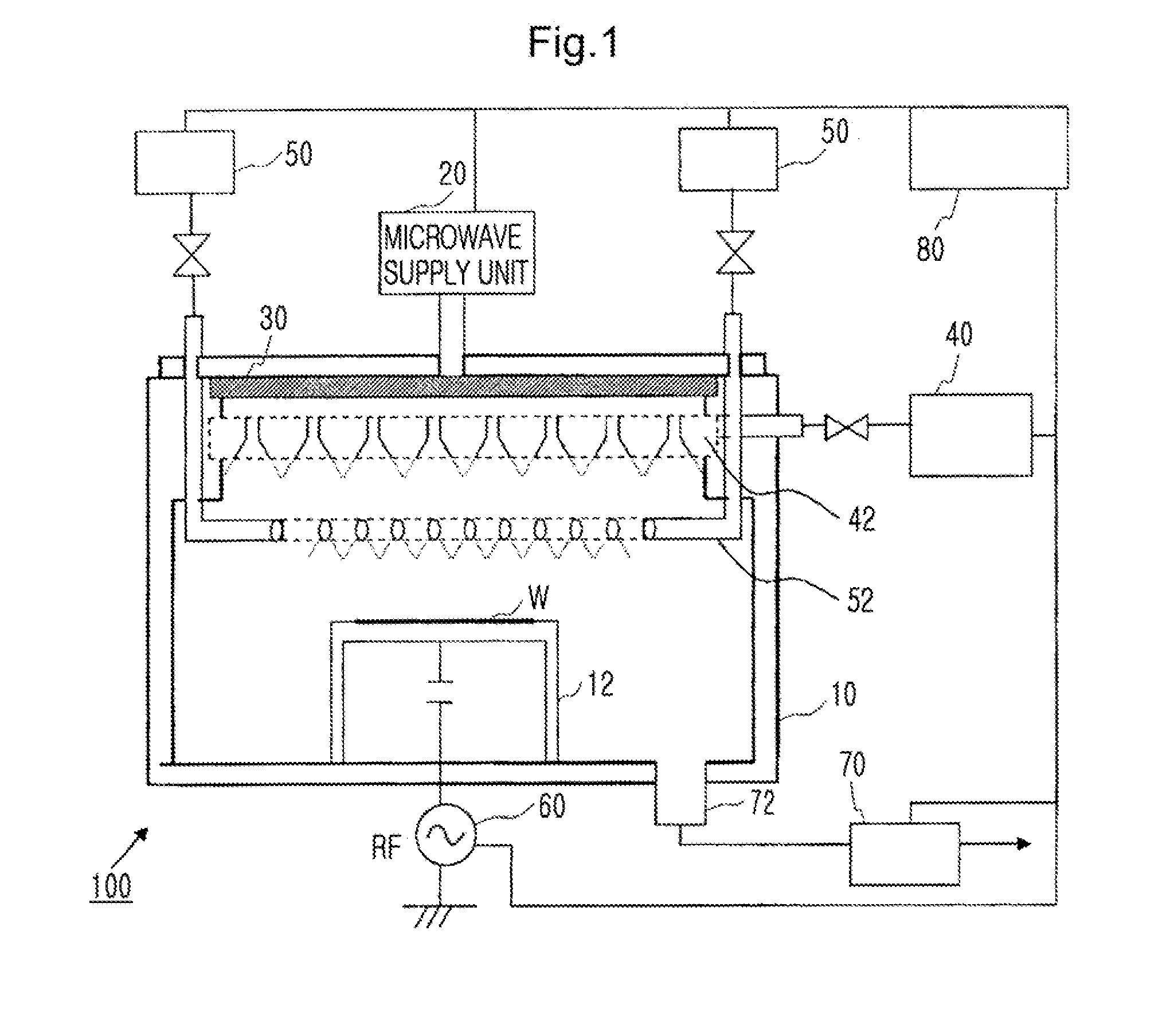
[0036]According to the present invention, in a process of supplying plasma excitation gas into a plasma excitation region formed above the substrate mounted on the base contained in a chamber, regulating pressure in the chamber, supplying raw gas into the chamber after introducing microwaves into the chamber, or introducing microwaves into the chamber after supplying raw gas into the chamber, and applying a substrate bias voltage to the substrate, the bias voltage functions as only a self-bias voltage without varying the plasma. The bias power is adaptively selected in accordance with the type of gas. Thus, irradiation ion energy on the surface of the substrate can be controlled.
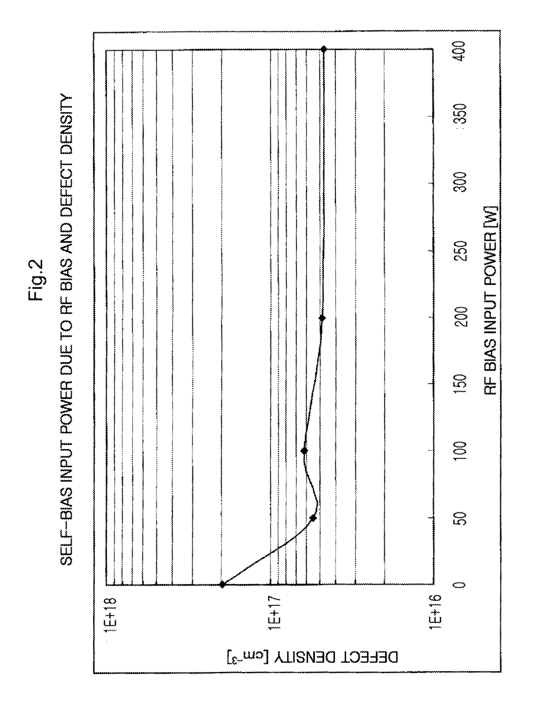
[0037]In other words, by introducing the microwaves, high-density plasma is generated, and a film can be formed at a high speed by using the high-density plasma. Simultaneously, since irradiation energy is controlled due to the substrate bias voltage applied by the bias voltage application unit, a dense film can be formed, and thus, even when the film is exposed to the air, oxygen is, to the maximum, prevented from mixing into the film, and thus a low oxygen concentration is achieved. Accordingly a high-quality film in which defect density of the film is reduced can be formed.
[0038]Also, when this is applied to the field of the photoelectric conversion element, a high-quality Si film having a low oxygen concentration and a lowered defect density can be formed so that reduction of dark conductivity (leakage current) and improvement of photoconductivity is promoted.
[0039]Also, in a tandem type solar cell, two layers are formed by stacking a first pin junction in which at least the i-layer including microcrystalline or polycrystalline silicon and a second pin junction in which at least the i-layer including microcrystalline or polycrystalline germanium so that a solar cell in which efficient use of incident light and improvement of an optical absorption characteristic can be further promoted, can be manufactured.
[0040]Also, in the tandem type solar cell, with respect to a first pin junction in which at least the i-layer including amorphous silicon, a second pin junction in which at least the i-layer including microcrystalline or polycrystalline silicon germanium, and a third pin junction in which at least the i-layer including microcrystalline or polycrystalline germanium, three layers may be formed by stacking the layers in the order of the first pin junction-second pin junction-third pin junction or the third pin junction-second pin junction-first pin junction, so that a solar cell in which efficient use of incident light and improvement of an optical absorption characteristic can be further promoted, can be manufactured.
[0041]Also, in a film formation process of the tandem type solar cell, by introducing microwaves, high-density plasma is generated, and a film can be formed at a high speed by using high-density plasma, and simultaneously, irradiation energy is controlled by applying the substrate bias voltage so that a film can be densified. Accordingly, even when the film is exposed to the air, oxygen is, to the maximum, prevented from mixing, and a oxygen concentration is lowered, and a high-quality film having a lowered defect density can be formed. In this regard, the solar cell having superior characteristics, such as lowering of dark conductivity (leakage current) and an increase of photoconductivity, i.e., the solar cell having high conversion efficiency can be manufactured.

Problems solved by technology

Conventional petroleum resources have problems, such as a limitation in resources, a so-called global warming phenomenon due to an increase in carbon dioxide that occurs in combustion, and the like.
Since the time for getting payback is considerably long, inevitably, a burden of an excessive cost(initial cost) is unavoidable, which becomes one of factors that make the wide use of solar cells practically difficult.

Method used


Image

  • Method for manufacturing photoelectric conversion elements
  • Method for manufacturing photoelectric conversion elements
  • Method for manufacturing photoelectric conversion elements

Examples


Embodiment Construction

[0050]Hereinafter, the present invention will be described in detail by explaining exemplary embodiments of the invention with reference to the attached drawings.

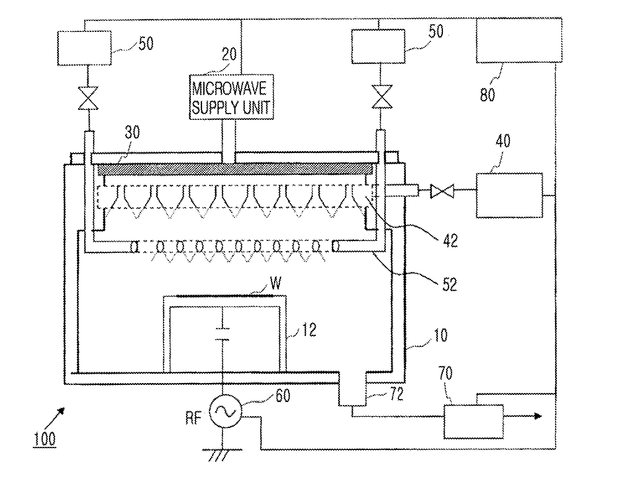
[0051]FIG. 1 is a conceptual view showing a schematic overall structure an apparatus for manufacturing photoelectric conversion elements, according to an embodiment of the present invention. Here, the apparatus for manufacturing a photoelectric conversion element is shown as an example for implementing the technical idea of the present invention. However, the idea of the present invention can be applied to a general film-forming apparatus for a semiconductor, and the following description includes descriptions of embodiments of the present application as a film forming apparatus•a film forming method. In the same drawing, only elements required for description of the present invention are shown, and a conventional technology has been employed for the other items.

[0052]As shown in the same drawing, a photoelectric conversion...


PUM

PropertyMeasurementUnit
temperatureaaaaaaaaaa
defect concentrationaaaaaaaaaa
radio frequencyaaaaaaaaaa

Abstract

“The invention provides a photoelectric conversion element manufacturing apparatus that forms a semiconductor stack film on a substrate by using microwave plasma CVD. The apparatus includes a chamber which is a enclosed space containing a base, on which the a subject substrate for thin-film formation is mounted, a first gas supply unit which supplies plasma excitation gas to a plasma excitation region in the chamber, a pressure regulation unit which regulates pressure in the chamber, a second gas supply unit which supplies raw gas to a plasma diffusion region in the chamber, a microwave application unit which applies microwaves into the chamber, and a bias voltage application unit which selects and applies a substrate bias voltage to the substrate according to the type of gas.”

Description

CROSS-REFERENCE TO RELATED PATENT APPLICATIONS[0001]This application is a divisional application of prior U.S. application Ser. No. 12 / 809,447, filed on Jul. 8, 2010, filed as application No. PCT / JP2008 / 003734 on Dec. 12, 2008, the entire contents of which are incorporated herein by reference, and this application claims the benefit of Japanese Patent Application No. 2007-326797, filed on Dec. 19, 2007, in the Japan Patent Office, the disclosure of which is incorporated herein in its entirety by reference.TECHNICAL FIELD[0002]The present invention relates to an apparatus and method for manufacturing photoelectric conversion elements, and a photoelectric conversion element, and more particularly, to an apparatus and method for manufacturing photoelectric conversion elements which are able to realize improvement of film formation speed and increase of conversion efficiency, and a photoelectric conversion element.BACKGROUND ART[0003]Conventional petroleum resources have problems, such ...

Claims


Application Information

Patent Timeline
Patent Type & Authority Applications(United States)
IPC IPC(8): H01L31/18
CPCH01L31/18C23C16/24C23C16/511H01L31/028H01L31/04H01L31/0745H01L31/1804H01L31/1812H01L31/1816Y02E10/547Y02P70/50C23C16/44
Inventor OHMI, TADAHIROTERAMOTO, AKINOBUGOTO, TETSUYATANAKA, KOUJI
Owner TOKYO ELECTRON LTD
Learn More