Process Utilizing High Performance Air-Cooled Combined Cycle Power Plant With Dual Working Fluid Bottoming Cycle and Integrated Capacity Control

a combined cycle and working fluid technology, applied in the direction of machines/engines, mechanical equipment, light and heating equipment, etc., can solve the problems of increasing the pressure on the industry to eliminate, water circulation rate, cooling system, etc., to reduce or eliminate the need for cooling water, reduce or eliminate the variation in the performance of the combined cycle plant

Active Publication Date: 2013-11-14
TAS ENERGY
View PDF11 Cites 29 Cited by
  • Summary
  • Abstract
  • Description
  • Claims
  • Application Information

AI Technical Summary

Benefits of technology

[0011]The current invention seeks to greatly reduce or eliminate the need for cooling water in large scale, combined cycle power plants while eliminating the drawbacks typically associated with air-cooled condensing bottoming cycles, Moreover, the current invention would greatly reduce or eliminate the variation in combined cycle plant performance of an air-cooled plant when compared to a water-cooled plant, particularly during periods of high demand and periods during the day or season when ambient temperatures are elevated.
[0013]Thus, the invention comprises a combined cycle power plant having a combustion turbine with a turbine inlet air cooling system to vary or maintain air mass flow going through the combustion turbine, a steam turbine topping cycle utilizing the exhaust of the combustion turbine as a heat source for producing steam, a steam turbine, and a steam condenser for condensing steam exiting the steam turbine. The invention further comprises an organic working fluid bottoming cycle having an expander to expand a heated vaporized organic working fluid and an air-cooled condenser for condensing the organic working fluid utilizing ambient air as the cooling medium. The steam condenser for condensing steam exiting the steam turbine also functions as an organic fluid vaporizer for the organic fluid bottoming cycle, vaporizing the organic fluid prior to introduction into the expander. Preferably the steam turbine topping cycle utilizes a steam turbine designed for a higher exiting steam temperature and pressure, such as a backpressure steam turbine, rather than the more common condensing steam turbines that are normally used on combined cycle plants. This new backpressure steam turbine is combined with the separate organic working fluid cycle to eliminate the need for the steam to be condensed in the air-cooled condenser. For purposes of the invention, the term “organic working fluid” is used to describe a second working fluid which may be any working fluid other than water and which has a vaporization temperature below that of water as described below. Organic working fluid may include, without limitation, ammonia (NH3) or other non-carbon working fluids.

Problems solved by technology

Constraints on cooling water supplies impact plant site and permitting decisions and current plant operations.
Furthermore, there is increasing pressure on the industry to eliminate once-through cooling systems.
However, replacing once through systems with the more common wet cooling towers may reduce the water circulation rate but does not reduce the overall water consumption (i.e., same amount of water is evaporated in the cooling process).
This results in large amounts of water evaporated for every MW-Hr of power produced.
However, various drawbacks to prior art air-cooled steam condensers exist.
However, operating the condenser below atmospheric pressure can lead to air infiltration which can lower the capacity output of the power plant and increase corrosion of power plant equipment, which increases the maintenance requirements of the boiler feedwater system, In addition, because steam has a comparatively large volume at low pressure, the back end sections of the steam turbine must be sized quite large for the large specific volume required for this very low pressure steam, thereby adding to the expense and complexity of the overall system.
One result is added capital cost.
Moreover, traditional air-cooled steam condensers are typically very large, A-frame designs with fans forcing ambient air up through the A-frame arranged condenser coils.
However, such A-frame designs impose added fan power requirements and do not represent ideal fan airflow across the coils, thereby inhibiting the effectiveness of the air-cooled condenser in the efficiency of the overall power system.
Another disadvantage of the prior art practice of utilizing air-cooled steam condensers for the bottoming cycle of combined cycle thermal power plants is that the output of the air-cooled combined cycle plant will be degraded more than that of the traditional water-cooled combined cycle plant because the air-cooled condenser rejects its heat to the higher dry bulb temperature rather than the colder wet bulb temperature of a water cooled combined cycle.

Method used


Image

  • Process Utilizing High Performance Air-Cooled Combined Cycle Power Plant With Dual Working Fluid Bottoming Cycle and Integrated Capacity Control
  • Process Utilizing High Performance Air-Cooled Combined Cycle Power Plant With Dual Working Fluid Bottoming Cycle and Integrated Capacity Control
  • Process Utilizing High Performance Air-Cooled Combined Cycle Power Plant With Dual Working Fluid Bottoming Cycle and Integrated Capacity Control

Examples


Embodiment Construction

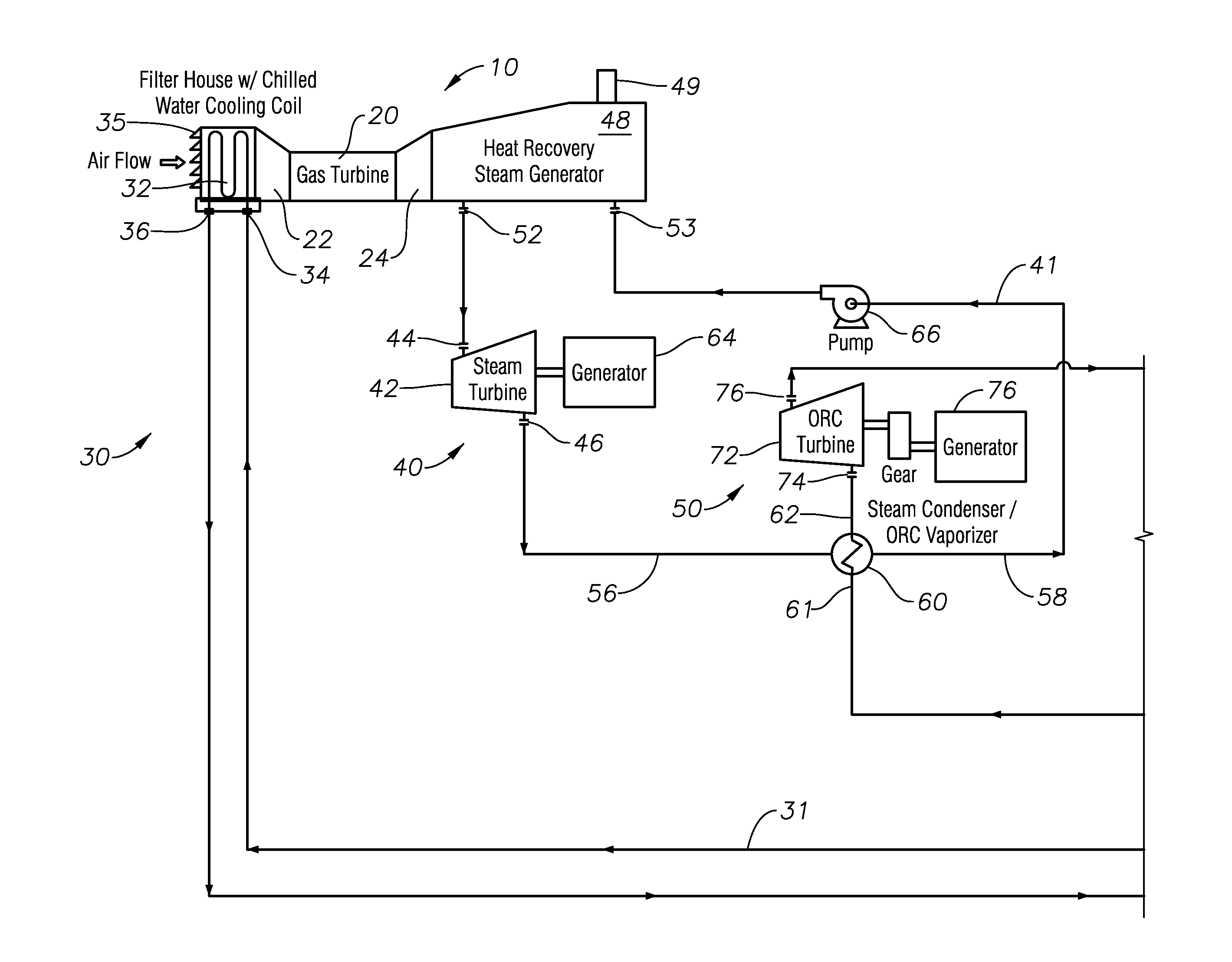
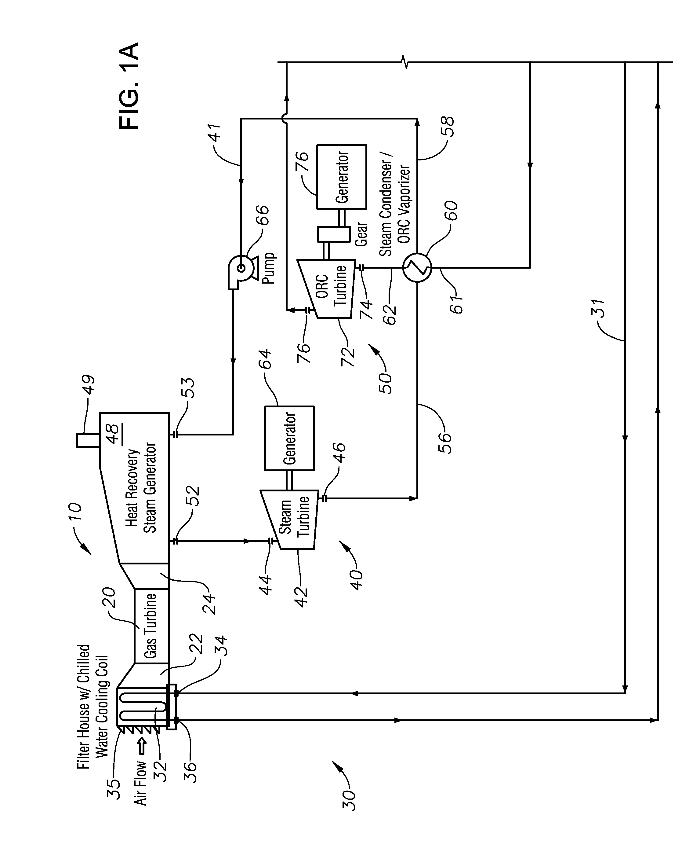
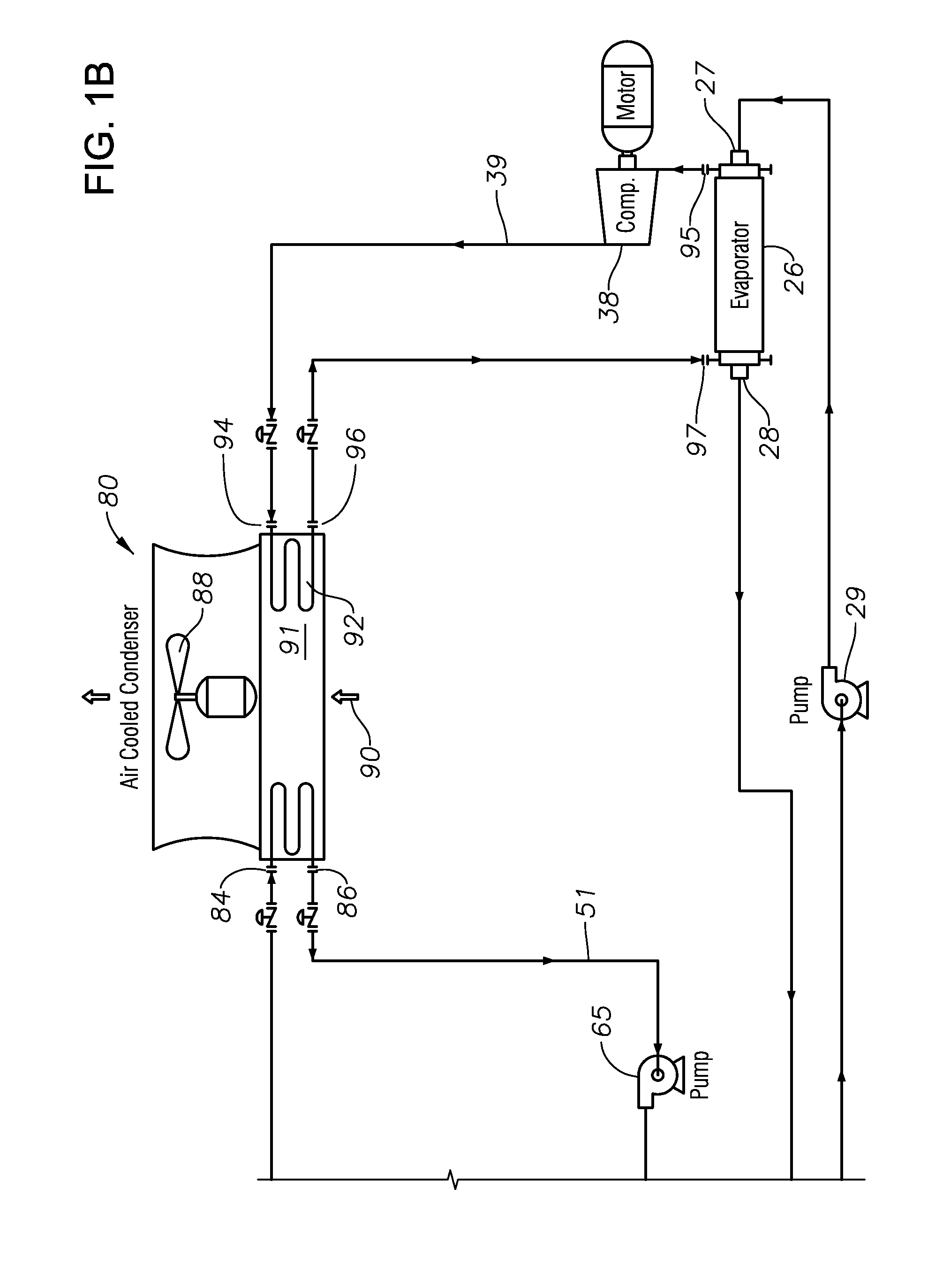
[0018]With reference to FIGS. 1A and 1B, there is shown a schematic of a. combined cycle power plant 10 of the invention, generally having a. combustion turbine 20, a turbine inlet cooling system 30, a steam turbine topping system 40, an organic fluid bottoming system 50, a steam condenser / organic vaporizer 60, and an air-cooled organic fluid condenser 80,

[0019]FIGS. 2A and 2B illustrate the same components of power plant 10 as FIGS. 1A and 1B, but includes an optional thermal energy storage system 100 and an optional condenser spray system 120, either of which can be used alone with the system of FIGS. 1A and 1B or in combination with one another as part of the system of FIGS. 1A and 1B.

[0020]In one preferred embodiment, combustion turbine 20 is a natural gas turbine having an air inlet 35 which would contain or be attached to an air cooling coil 32 of the turbine inlet cooling system 30. The air cooling coil 32 utilizes chilled water circulated therethrough to cool the inlet air t...


PUM


Abstract

A combined cycle power plant system and methods of operation so as to minimize consumption of cooling water utilizes exhaust from a combustion turbine to generate steam for power generation in a steam turbine topping cycle. The exhaust steam from the steam turbine topping cycle is utilized to vaporize an organic working fluid in an organic working fluid bottoming cycle, where vaporized organic working fluid expanded across a turbine generates additional power. Exhaust gas from the organic working fluid bottoming cycle is condensed utilizing an air-cooled heat exchanger. Heat exchange bundles of the air-cooled heat exchanger are preferably arranged horizontally relative to the ground to maximize efficiency. Turbine inlet cooling is employed at the combustion turbine to recapture energy lost in the system. A thermal energy storage tank may be utilized in conjunction with the turbine inlet cooling to supply chilling water to the system.

Description

PRIORITY[0001]This application is a divisional of and claims priority to U.S. Non-Provisional application Ser. No. 13 / 586,673 entitled, “HIGH PERFORMANCE AIR-COOLED COMBINED CYCLE POWER PLANT WITH DUAL WORKING FLUID BOTTOMING CYCLE AND INTEGRATED CAPACITY CONTROL,” filed Aug. 17, 2012, naming Thomas L. Pierson and Herman Leibowitz as inventors, which is a non-provisional of and claims priority to U.S. Provisional Application No. 61 / 624,824, having the same title, filed Apr. 16, 2012, also naming Thomas L. Pierson and Herman Leibowitz as inventors, the disclosure of each being hereby incorporated by reference in their entiretyBACKGROUND OF THE INVENTION[0002]The reduction of water consumption and use is emerging as a top priority for all types of power plants as a result of water supply constraints in many regions of the world. Several factors contribute to intensified water scarcity, including increased demands for electricity, increased water use in other sectors (for example, agri...

Claims


Application Information

Patent Timeline
Patent Type & Authority Applications(United States)
IPC IPC(8): F01K23/10
CPCF01K23/10F02C3/28F05D2220/75Y02E20/16F01K25/106F22B1/028F22B1/1815Y02E50/10Y02P80/15
Inventor PIERSON, THOMAS L.LEIBOWITZ, HERMAN
Owner TAS ENERGY
Why Eureka
Try Eureka