Thermoelectric converter element, method of manufacturing thermoelectric converter element, and thermoelectric conversion method
a technology of thermoelectric converter and thermoelectric converter, which is applied in the manufacture/treatment of thermoelectric devices, generators/motors, thermoelectric devices, etc., can solve the problems of difficult to obtain a low thermal conductivity and difficult to hold a temperature difference between a front face and a rear face of the element, and achieve excellent conversion efficiency and high productivity.
- Summary
- Abstract
- Description
- Claims
- Application Information
AI Technical Summary
Benefits of technology
Problems solved by technology
Method used
Image
Examples
example 1
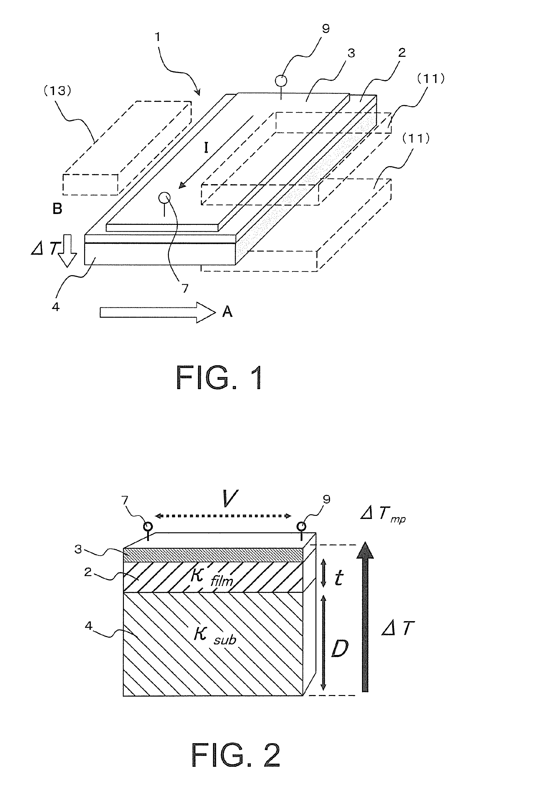
[0156]A thermoelectric converter element 1 according to the first embodiment was produced, and a thermoelectromotive force of the thermoelectric converter element 1 was evaluated. Specific procedures were as follows.
[0157]
[0158]FIG. 9 shows an example of the thermoelectric converter element produced. A substrate (111) surface of gadolinium gallium garnet (with composition of Gd3Ga5O12; hereinafter referred to as “GGG”) manufactured by Saint-Gobain K. K. was prepared. The thickness of the substrate was 0.7 mm, and the substrate had a rectangular shape with planar dimension of 2 mm×4 mm
[0159]Then a film of yttrium iron garnet (with composition of BiY2Fe5O12; hereinafter referred to as “Bi:YIG”) in which Bi had been substituted for part of the Y sites was deposited as a magnetic film 2 on the GGG substrate by a metal organic decomposition method (MOD method).
[0160]Specifically, a MOD solution with a mole fraction of Bi:Y:Fe=1:2:5 that had been manufactured by Kojundo Chemical Lab. Co.,...
example 2
[0206]In Example 1, an MOD method is used to deposit the magnetic film 2. In this case, high-temperature sintering is required for crystallization. Therefore, when the substrate 4 is made of a material that is likely to be decomposed at temperatures not more than a sintering temperature, such as plastics, then deposition is difficult to be performed. Additionally, the thickness and the number of layers are difficult to be increased because deposition is performed by spin-coating. Thus, in Example 2, deposition of the magnetic film 2 was attempted with use of an aerosol deposition method (AD method; for details of the AD method, see, e.g., Journal of the Surface Science Society of Japan, Vol. 25, No. 10, pp. 635-641), which can achieve high-speed thick film growth of a magnetic material.
[0207]In this example, a film of yttrium iron garnet (with composition of Bi0.5Y2.5Fe5O12 in this example) in which Bi had been substituted for part of the Y sites was deposited as a magnetic film 2 o...
example 3
[0227]A thermoelectric converter element 1a according to the second embodiment was produced, and the thermoelectromotive force was evaluated. Specific procedures were as follows.
[0228]
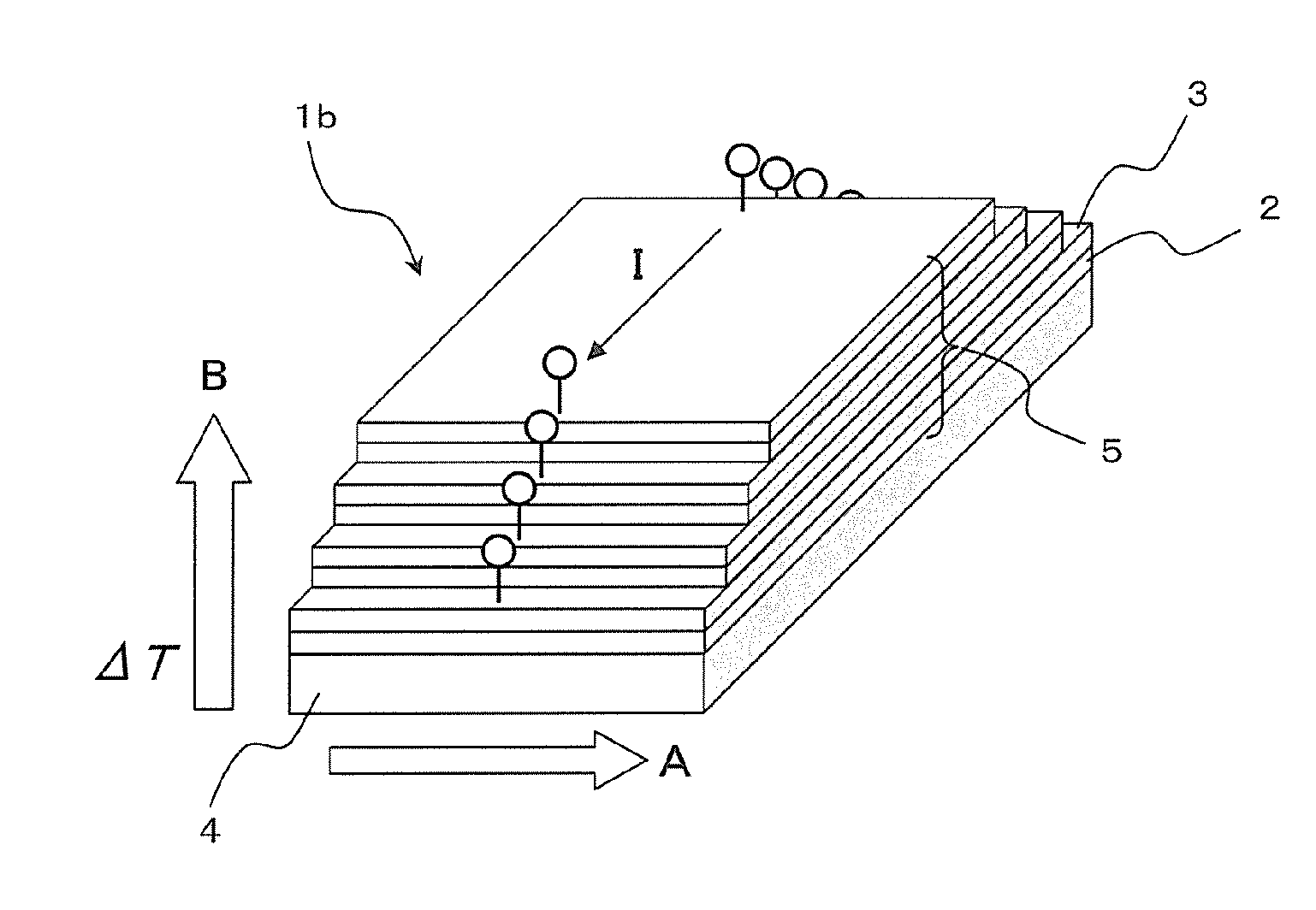
[0229]First, a substrate (100) surface of gadolinium gallium garnet (GGG) manufactured by NTT Electronics Corporation was prepared as a substrate 4. The substrate had a thickness of 0.7 mm and a planar dimension of 2 mm×4 mm.
[0230]Next, yttrium iron garnet (with composition of BiY2Fe4GaO12; hereinafter referred to as Bi, Ga:YIG) in which Bi had been substituted for part of the Y sites and Ga had been substituted for part of the Fe sites was deposited as a magnetic film 12 on the substrate 4 by a metal organic decomposition method (MOD method).
[0231]Specifically, a MOD solution with a mole fraction of Bi:Y:Fe:Ga=1:2:4:1 that had been manufactured by Kojundo Chemical Lab. Co., Ltd. was used. (Within this solution, raw metal materials were dissolved in acetic ester at a concentration of 3%.) This solution...
PUM
 Abstract
Description
Claims
Application Information
 - R&D
- Intellectual Property
- Life Sciences
- Materials
- Tech Scout
- Unparalleled Data Quality
- Higher Quality Content
- 60% Fewer Hallucinations
Browse by: Latest US Patents, China's latest patents, Technical Efficacy Thesaurus, Application Domain, Technology Topic, Popular Technical Reports.
© 2025 PatSnap. All rights reserved.Legal|Privacy policy|Modern Slavery Act Transparency Statement|Sitemap|About US| Contact US: help@patsnap.com


