
Electrospinning process for fiber manufacture

Active Publication Date: 2013-11-28
ARSENAL MEDICAL
View PDF0 Cites 5 Cited by
  • Summary
  • Abstract
  • Description
  • Claims
  • Application Information

AI Technical Summary

Benefits of technology

The present invention is a system and method for high-throughput production of core-sheath fibers using electrospinning. The invention includes a device with a hollow tube and structural features for efficient production of fibers. Additionally, the invention includes a collector for electrospun yarns in yarn form, which can be rotated to twist fibers into yarns. The invention is advantageous in enabling high-throughput production of high-quality core-sheath fibers and electrospun yarns.

Problems solved by technology

None of these methods, however, are ideally suited to producing drug-loaded core-sheath fibers, as they all utilize high temperatures which may be incompatible with thermally labile materials such as drugs or polypeptides.
Core-sheath fibers have been produced using emulsion-based electrospinning methods, which exploit surface energy to produce core-sheath fibers, but which are limited by the relatively small number of polymer mixtures that will emulsify, stratify, and electrospin.
However, both emulsion and coaxial electrospinning methods can have relatively low throughput, and are not ideally suited to large-scale production of core-sheath fibers.
To increase throughput, coaxial nozzle arrays have been utilized, but such arrays pose their own challenges, as separate nozzles may require separate pumps, the multiple nozzles may clog, and interactions between nozzles may lead to heterogeneity among the fibers collected.
The Nanospider® improves throughput relative to other electrospinning methods, but it is not currently possible to manufacture core-sheath fibers using the Nanospider®.

Method used


Image

  • Electrospinning process for fiber manufacture
  • Electrospinning process for fiber manufacture
  • Electrospinning process for fiber manufacture

Examples


example 1

Formation of Homogeneous Fibers

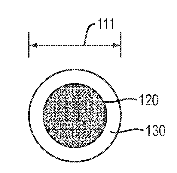
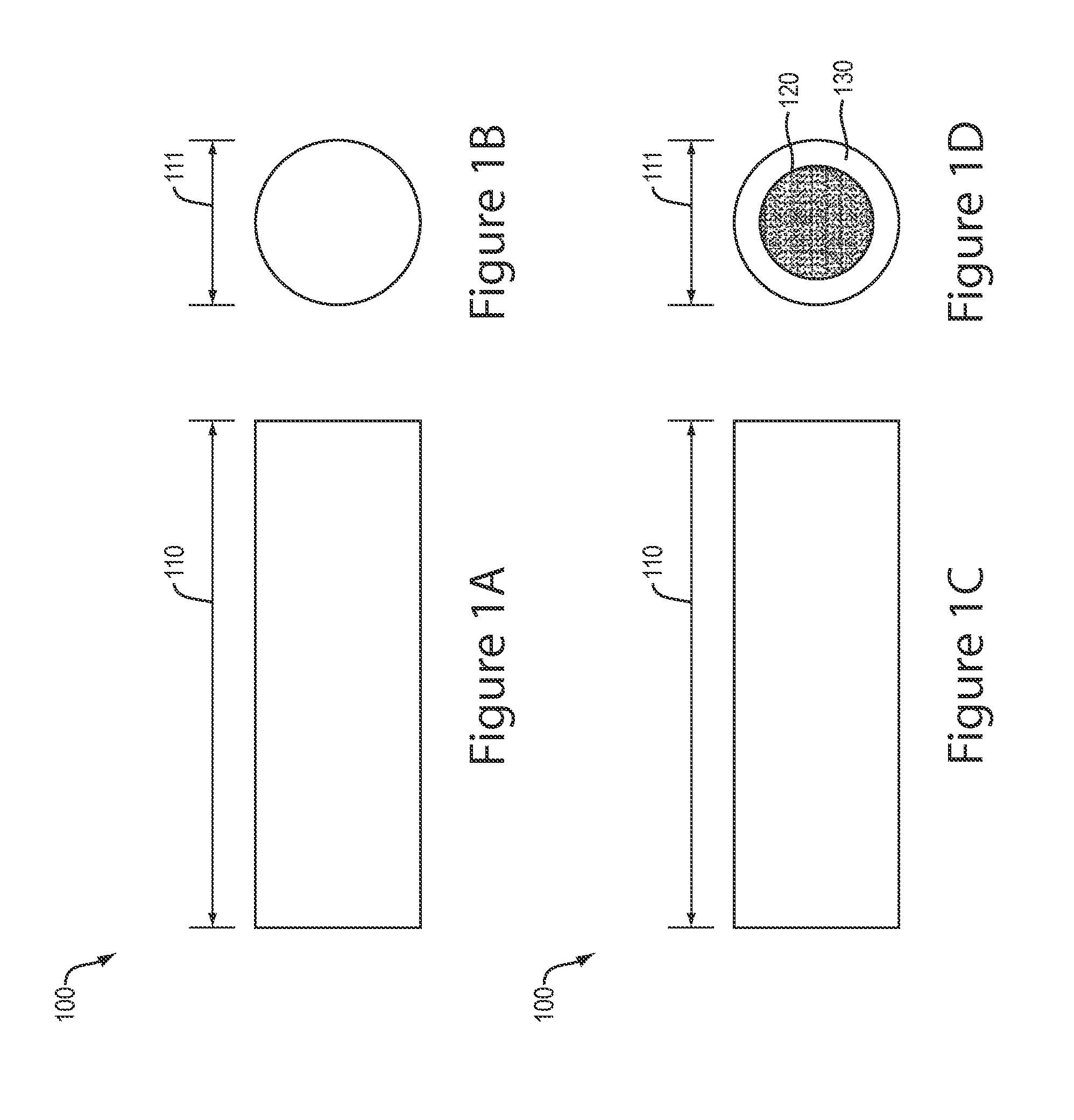
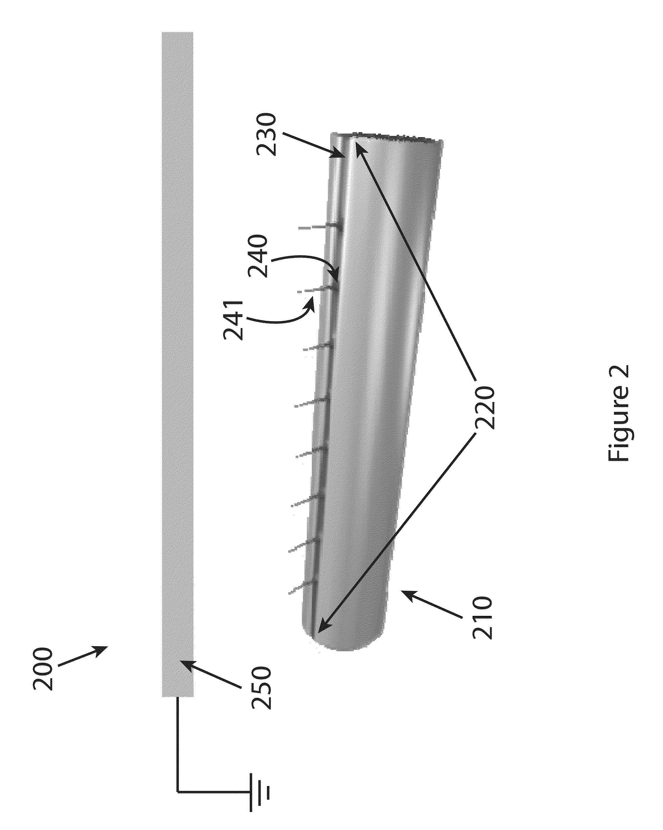
[0030]Homogeneous fibers made of poly(lactic co-glycolic acid) (L-PLGA) were manufactured in accordance with the present invention. A solution containing 4.5 wt % of 85 / 15 L-PLGA in hexafluoroisopropanol was pumped into one end of a 10 cm long hollow tube (1 cm diameter) having a 0.4 cm slit of the present invention at a rate of 8 milliliters per hour. A grounded, flat, rectangular collecting plate was placed approximately 15 centimeters from the slit of the cylinder, and a voltage of 25-35 kV was applied, and the resultant fibers were collected on the collecting plate and examined under scanning electron microscopy as illustrated in FIG. 7b.

example 2

Formation of Core-Sheath Fibers

[0031]Core-sheath fibers were manufactured in accordance with the present invention, as shown in FIG. 8a. A rhodamine-containing core solution containing 15 wt % polycaprolactone in a 3:1 (by volume) chloroform:acetone solution was pumped through a hollow cylindrical tube having a slit therethrough at a rate of 10 ml / hour. Jets were formed by applying a voltage of 25 kV. Once the Taylor cones were stable, a syringe pump and needle filled with a fluorescein-containing sheath solution containing 15 wt % polycaprolactone in a 6:1 (by volume) chloroform:methanol solution was placed so that the needle was adjacent to one of the Taylor cones, and the sheath solution was pumped at a rate of 6 ml / hour. To verify the core-sheath structure of the resulting fibers, fluorescence micrographs were obtained which demonstrated that the rhodamine-containing core component was indeed surrounded by the fluorescein-containing sheath component, as shown in FIG. 8b.


PUM

PropertyMeasurementUnit
Lengthaaaaaaaaaa
Lengthaaaaaaaaaa
Diameteraaaaaaaaaa

Abstract

Devices and methods for high-throughput manufacture of concentrically layered nanoscale and microscale fibers by electrospinning are disclosed. The devices include a hollow tube having a lengthwise slit through which a core material can flow, and can be configured to permit introduction of sheath material at multiple sites of Taylor cone formation formation.

Description

FIELD OF THE INVENTION[0001]The present invention relates to systems and methods for the manufacturing of microscale or nanoscale concentrically-layered fibers by electrospinningCROSS REFERENCE TO RELATED APPLICATIONS[0002]The present invention claims priority to U.S. Provisional Application No. 61 / 437,886 entitled “Electrospinning Process for Fiber Manufacture,” filed Jan. 31, 2011; and to U.S. application Ser. No. 13 / 362,467 entitled “Electrospinning Process for Manufacture of Multi-Layered Structures,” filed Jan. 31, 2012.BACKGROUND[0003]Macro-scale structures formed from concentrically-layered nanoscale or microscale fibers (“core-sheath fibers”) are useful in a wide range of applications including drug delivery, tissue engineering, nanoscale sensors, self-healing coatings, and filters. On a commercial scale, the most commonly used techniques for manufacturing core-sheath fibers are extrusion, fiber spinning, melt blowing, and thermal drawing. None of these methods, however, are...

Claims


Application Information

Patent Timeline
IPC IPC(8): D01D5/00C01D5/00
CPCD01D5/0069D01D5/0038D01D5/0076D01D5/34
Inventor SHARMA, UPMAPHAM, QUYNHMARINI, JOHN
Owner ARSENAL MEDICAL
Features
  • Generate Ideas
  • Intellectual Property
  • Life Sciences
  • Materials
  • Tech Scout
  • Unparalleled Data Quality
  • Higher Quality Content
  • 60% Fewer Hallucinations
Learn More