
Plasma Oil-free Ignition System in Oxygen Enriched Environment

an oxygen-enriched environment and ignition system technology, applied in the field of thermodynamic boilers, can solve the problems of poor adaptability of plasma ignition technology to coal with poor combustion performance, poor combustion performance, etc., and achieve low volatile matter content, low calorific value, and high ash content

Active Publication Date: 2013-12-19
ZHENG LU +3
View PDF1 Cites 7 Cited by
  • Summary
  • Abstract
  • Description
  • Claims
  • Application Information

AI Technical Summary

Benefits of technology

This invention is about a plasma oil-free ignition system that works in an oxygen-enriched environment. It has a simple construction and can be used with different types of coal, especially those with low volatile matters. The technical effect of this patent is to provide a reliable and efficient way to ignite coal without using oil-based methods that can pollute the environment.

Problems solved by technology

Firstly, the plasma ignition technology has higher requirements for coal quality. At present, plasma ignition has been successfully applied to a great amount of domestic power station boilers with bituminous coal as steam coal, and the cause for this is that bituminous coal has higher dry ash-free basis volatile matter content (generally 30%-35%), and the pulverized coal air flow is easily ignited. However, the plasma ignition technology is poorly adaptable to coal with low volatile matter content like anthracite, meager coal and poor bituminous coal. Successful application of the plasma ignition technology is seldom reported for meager coal boilers in China, and the successful application of the plasma ignition technology to anthracite boilers has not been reported at present.
Secondly, during boiler ignition, energy of plasma generators is generally about 100-200 KW, which is not enough to ignite all pulverized coal. Practices show that the boilers subject to the plasma ignition technology experience high carbon content of fly ash at initial starting stage, and a large amount of pulverized coal is not burnt out, especially the coal difficult to be bunt out has worse burnout performance. Unburnt pulverized coal is easy to accumulate at corrugated plates of air preheaters or catalyst injection places of SCR reactors, thus easily resulting in secondary combustion of the unburnt pulverized coal and further causing major accidents and economic losses;
Thirdly, during boiler ignition, for ensuring stable ignition of the pulverized coal, generally the pulverized coal with higher concentration is used during actual operation, causing higher load and larger temperature rise speed of the boilers during starting, which easily gives rise to overtemperature at steam sides and results in accidents like bursting of pipes of superheaters due to overtemperature.

Method used


Image

  • Plasma Oil-free Ignition System in Oxygen Enriched Environment
  • Plasma Oil-free Ignition System in Oxygen Enriched Environment
  • Plasma Oil-free Ignition System in Oxygen Enriched Environment

Examples


embodiment 1

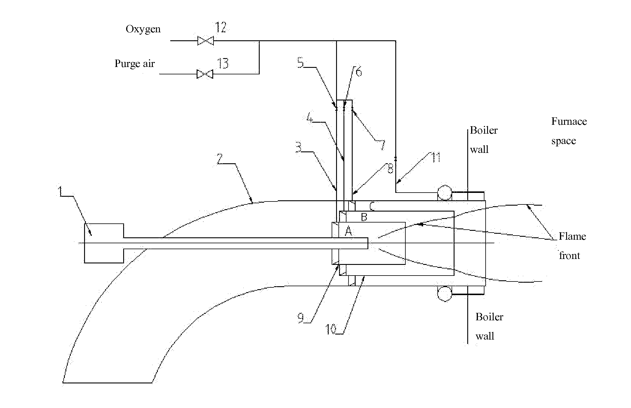
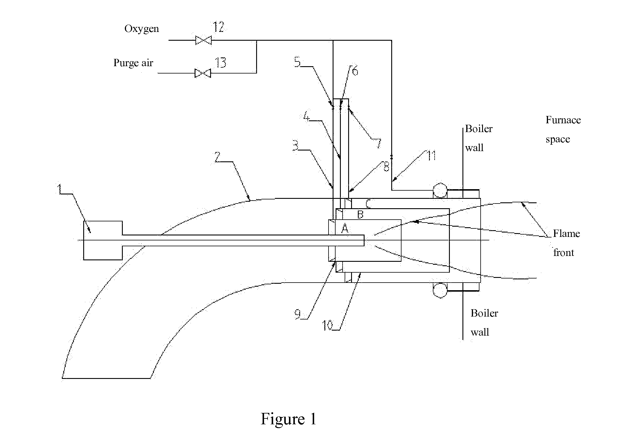
[0039]As shown in FIG. 1, FIG. 3 and FIG. 4, the invention provides a plasma oil-free ignition system in oxygen enriched environment which comprises a plasma generator 1 and a burner 2. The burner 2 comprises a sleeve 9 and a sleeve 10 therein, and the plasma generator 1, the burner 2, the sleeve 9 and the sleeve 10 are arranged coaxially. An annular space A exists between the sleeve 9 and the plasma generator 1, and an oxygen duct 3 is arranged on the inner wall at the left end of the sleeve 9. Besides providing oxygen, the oxygen duct 3 also acts as a pulverized coal concentration ring. A wear resistant metal is overlaid to wall of the oxygen duct 3 toward direction of pulverized coal air flow. Wall of the oxygen duct 3 against the direction of the pulverized coal air flow is provided with an annular groove 101. Oxygen enters the annular space A through the annular groove 101 to mix with pulverized coal so as to form local oxygen enriched zones in the annular space A and adjacent ...

embodiment 2

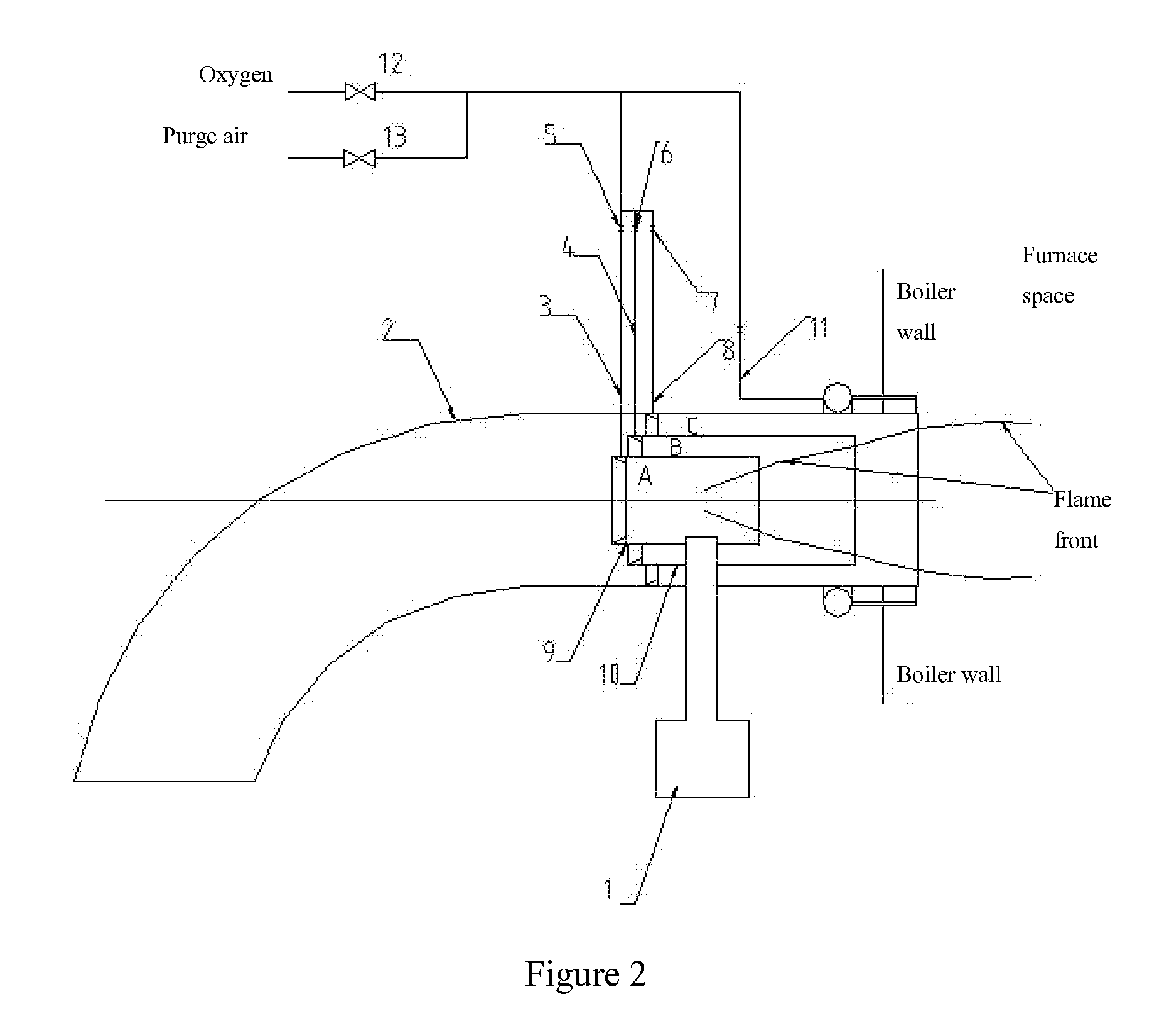
[0042]As shown in FIG. 2, FIG. 3 and FIG. 4, the distinction between the embodiment and the embodiment 1 is that the plasma generator is inserted into the plasma burner from the radial direction of the burner 1, and the sleeve 9 is filled with the high temperature plasmas jetted by the plasma generator.

embodiment 3

[0043]As shown in FIG. 5, the distinction between the embodiment and the embodiment 1 is that cross sections of the oxygen ducts 3, 4 and 8 are triangular, and their walls toward the direction of the pulverized coal air flow are arc walls; and walls of the oxygen ducts 3, 4 and 8 against the direction of the pulverized coal air flow are provided with annular grooves 101, and oxygen enters the burner through the annular grooves 101 to mix with pulverized coal.


PUM


Abstract

A plasma oil-free ignition system in oxygen enriched environment comprises a plasma generator and a burner. The plasma oil-free ignition system comprises a sleeve group coaxially arranged with the burner, and the sleeve group comprises multiple coaxially sleeved sleeves. Annular spaces are formed between adjacent sleeves and between the sleeves and the burner. Oxygen ducts are arranged on the sleeves, and oxygen ducts are arranged on the burner. Plasmas jetted by the plasma generators form a local high temperature zone filled with high temperature plasma and pulverized coal air flow. A certain amount of oxygen is fed to the burner through the oxygen duct therein to form local oxygen enriched zones in the annular spaces and the subsequent adjacent spaces through which air flows, thus realizing oxygen enriched combustion of volatile matters or coke or mixture thereof, and combustion the pulverized coal air flow more intensely to release more heat so as to ignite the primary air pulverized coal air flow quickly and burn the pulverized coal air flow stably. The invention has simple structure, is applicable to different coal types, especially applicable to the plasma oil-free ignition system in oxygen enriched environment of coal types with low volatile matters.

Description

FIELD OF THE INVENTION[0001]The invention belongs to the field of thermodynamic boilers, and relates to boiler fittings, in particular to a plasma oil-free ignition system in oxygen enriched environment.DESCRIPTION OF THE RELATED ART[0002]The conventional power station boilers are commonly ignited by oil guns. For ignition starting of a boiler, an oil gun is ignited, and a furnace is heated to ignition temperature of pulverized coal air flow after oil is burnt in the furnace for a certain time, and pulverized coal is blown into the furnace for mixed combustion of oil and coal. When the load of the boiler is more than 50% and the pulverized coal air flow can be burnt stably, fuel oil is gradually removed to finish the ignition starting process of the boiler. In order to save cost and reduce the fuel oil consumption of the power station boilers, a lot of foreign and domestic companies have developed plasma oil-free ignition technologies which have been widely applied to a great amount...

Claims


Application Information

Patent Timeline
Patent Type & Authority Applications(United States)
IPC IPC(8): F02P23/00
CPCF02P23/00F23Q7/02F23D1/00F23D2207/00Y02E20/34Y02E20/32
Inventor ZHENG, LUZHANG, JIANWENZHAO, YANGLI, YUEHUA
Owner ZHENG LU
Learn More